In this paper, two different Class D (conversion mode) amplifier technologies, pulse width modulation (PWM) and spread spectrum modulation, are discussed. Traditionally, PWM Class D amplifiers require large and expensive filtering components to reduce electromagnetic interference caused by their rail-to-rail amplitude and fast switching frequency. The spread-spectrum modulation technology used in today's Class D amplifiers allows designers to eliminate these filtering components without degrading audio performance or amplification.
This article refers to the address: http://
introduction
Class D amplifiers are more attractive to portable audio application designers because they work better than Class A and Class B amplifiers. However, some designers have not used Class D amplifiers in portable applications because traditional PWM Class D amplifiers require a large number of expensive filtering components to reduce electromagnetic interference. Maxim's Class D amplifier spread-spectrum modulation technology allows designers to eliminate these filtering components without degrading audio performance or amplification, thus facilitating the promotion of efficient Class D amplifiers in portable audio applications.
Traditional Pulse Width Modulation Amplifier Topology
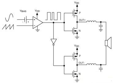
Figure 1 shows a typical PWM bridged load class D amplifier. This approach utilizes an internally generated sawtooth waveform as a reference for the input stage. One of the comparators monitors the analog input voltage and compares it to the sawtooth waveform. When the input to the sawtooth waveform exceeds the input voltage, the output of the comparator is reduced. Therefore, a converter is used at the output of the comparator to generate a complementary PWM waveform for the second leg of the BTL output.
Because its rail-to-rail amplitude and fast switching frequency produce high RF emissions and interference, a PWM amplifier typically requires a large number of filtering components at the output. At this point, an LC filter is typically required to reduce this high frequency interference and extract the audio content from the duty cycle of the PWM signal.

Figure 1. Traditional Pulse Width Modulation Topology
Spread spectrum modulation amplifier topology
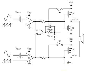
One way to replace this expensive large-output LC filter solution is to improve the conversion process so that the amplifier can keep efficiencies while maintaining efficiency. Maxim's Class D amplifier does just that. Its Class D amplifiers feature a unique patented spread-spectrum modulation mode that dwarfs broadband spectral components and minimizes EMI from speaker and wiring. Figure 2 shows the topology of this Class D amplifier using Maxim's MAX9700 Class D amplifier.
Maxim's Class D amplifier modulation scheme uses an internally generated sawtooth waveform with a complementary signal pair in the input section. If there is no complementary input signal, a differential input is generated inside the IC.

Figure 2: Mono Class D Amplifier Topology
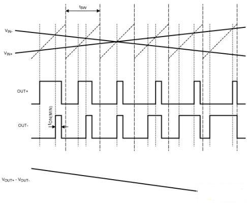
The comparator monitors the input of the Class D amplifier and compares the supplemental input voltage to the sawtooth waveform. When the sawtooth waveform exceeds the input voltage, comparator A emits a zero volt signal that pulls the corresponding Class D output (OUT+) high to VDD. When the sawtooth waveform exceeds its input voltage, comparator B outputs a zero volt at the output, which also pulls the corresponding Class D output (OUT-) high to VDD. After both Class D outputs are pulled high, a timer starts at a simple NOR gate output with a time constant of tau, which is equivalent to 1 / (RTON * CTON). During a fixed time (tau), both Class D outputs are pulled high to GND and both comparators are reset. This sequence produces a minimum width pulse tON(MIN) at the output of the second comparator. As the input voltage increases or decreases, the pulse duration of one of the outputs (the first comparator will trip) will rise, while the duration of the pulse on the other output will remain at tON(MIN), resulting in The net voltage of the speaker (VOUT+ - VOUT-) changes.

Figure 3: Maxim's Class D BTL output with input signal FFM mode
Fixed frequency modulation and spread spectrum modulation
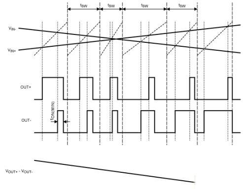
Maxim's Class D technology uses two modulation modes: (1) fixed frequency modulation (FFM) mode and (2) spread spectrum modulation mode. In FFM mode (Figure 3), the duration of the sawtooth waveform remains the same, which is the same as in the traditional PWM scheme. In the spread spectrum modulation mode (Figure 4), the duration of the sawtooth wavelength is constantly changing in each cycle (typically ±10%). Figure 4 magnifies the amount of change in the sawtooth waveform to better show the effect.

Figure 4: Maxim's Class D BTL output with input signal spread spectrum modulation mode
Spread spectrum modulation mode minimizes EMI interference
Maxim's spread-spectrum technology allows Class D amplifiers to actually discard filters and work as long as the speaker lines are not too long. Large output LC filters are typically required for conventional PWM architectures to ensure that consumer products containing Class D amplifiers are capable of complying with EMC specifications. Maxim's proprietary spread spectrum technology reduces the radiation of Class D amplifiers to meet electromagnetic compatibility requirements without the need for filtering at the output or with minimal filtering (see Appendix).
Electromagnetic compatibility requires molded products to pass existing quasi-peak detection limits - such as those imposed by CE (European Community, European Standard) and FCC (Federal Communications Commission, US Standard) - to ensure minimum electromagnetic interference is maintained. Electromagnetic interference interrupts, obstructs or reduces the effective performance of electrical and electronic equipment as defined by CE and FCC. In quasi-peak detection, the measured signal level is measured by the repetition frequency of the spectral components of the signal. The lower the repetition rate, the lower the quasi-peak value displayed.
Spread-frequency modulation fully exploits the quasi-peak detection and greatly reduces electromagnetic interference (Table 1). In the spread spectrum modulation mode, the peak fundamental frequency of the Class D amplifier can be any value within a certain range - typically ±10% from its fundamental switching frequency. Assuming that the quasi-peak detection is performed in the analyzer with a resolution bandwidth of 120 kHz, then in addition to the basic switching frequency and the first few harmonics, the switching frequency is only displayed for a period of time in any of the center frequencies.
to sum up
The near-rail-to-rail amplitude and fast switching frequency of Class D amplifiers can cause high RF emissions and interference. When audio content is copied to the drive, it is generally necessary to use a large and expensive LC filter to reduce this interference. But now, Maxim's spread-spectrum modulation technology enables Class D amplifiers to achieve low-power "no-filter" operation with an efficient PCB layout and relatively short speaker lines.
appendix
Overview of filtering technology
There are three filter topologies for Class D power amplifiers: (1) FB-C: ferrite beads and capacitors; (2) LC: inductors and capacitors; and (3) "no filter" technology. Which filtering technique should be chosen for a particular design depends on the length of the speaker cable and the PCB layout. The following are the advantages and disadvantages of these three filter topologies:
FB-C filtering
When the speaker line path is reasonable, the FB-C filtering is sufficient to meet the electromagnetic compatibility requirements. Compared with LC filtering, the FB-C filtering scheme is more streamlined and efficient. However, since it can only be effective when the frequency is greater than 10 MH, the application range of FB-C filtering is greatly limited. Moreover, even at frequencies below 10 MHz, filtering is not possible if the speaker line path is unreasonable.
LC filtering
In contrast, LC filtering can take effect at a frequency of approximately 30 kHz. When the speaker cable used in a design is long and the PCB layout is not very good, LC filtering is undoubtedly an "insurance" option. However, LC filtering requires expensive and bulky external components, which is clearly not suitable for portable devices. Moreover, when the frequency is greater than 30MHz, the main inductor will self-resonate, and LC filtering will require additional components to suppress electromagnetic interference.
"No Filter" Filtering ("Filterless" Filtering)
The “filterless†amplifier topology is the most efficient solution because it eliminates the need for additional filtering components. With this solution, Class D amplifiers with shorter twisted pair speaker cables are fully compliant with electromagnetic compatibility standards. However, as with FB-C filtering, if the speaker line path is unreasonable, this scheme may not be able to suppress electromagnetic interference. Also note that Maxim's Class D amplifiers can also be "filterless", as long as the speaker is sensed at the conversion frequency of the amplifier. When the output voltage is converted, the high inductance at the switching frequency keeps the overload current relatively constant.
heat shrink tube is typically used in applications where there is no need for additional protection against moisture or other environmental factors. It is available in various sizes and colors to accommodate different wire and cable diameters.
The installation process involves sliding the heat shrink tube over the item to be covered and then applying heat, usually with a heat gun, to shrink the tube and create a secure fit. This process provides insulation and protection against abrasion, chemicals, and other potential damage.
heat shrink tube is commonly used in electronics, automotive, aerospace, and other industries where wire and cable management is important. It is a cost-effective solution for protecting and organizing electrical components.
Single Wall Heat Shrink Tube,Heat Resistant Tubing,Pvc Heat Shrink Film Tubing,Heat Shrink Insulating Tube
Dongguan Liansi Electronics Co.,Ltd , https://www.liansielectronics.com