The popularity of wireless charging can be said to benefit from the rapid development of the electric vehicle industry, because the problem of charging a large amount of wired charging piles, complicated operation, and high wear rate for electric vehicles has always plagued the users of electric vehicles. This has promoted the rapid development of wireless charging technology. Here, the wireless charging of electric vehicles is mainly analyzed and shared.
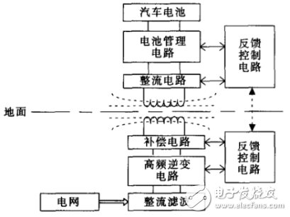
1.1 Electric vehicle inductive wireless charging principleInductive wireless charging technology has been successfully applied to some electric vehicle charging systems. The transmitting system is buried below the ground. The receiving coil is generally located in the chassis of the car. The transmitting coil is inductively coupled to the receiving coil, which is equivalent to a separable transformer. The electric energy is wirelessly transmitted through the high-frequency electromagnetic field between the coils, and the basic structure thereof is as shown in FIG.
It can be seen that first of all, the power frequency AC power from the power grid is converted into high frequency alternating current by rectification and inverter. This frequency is generally several tens to several hundred KHz, and the current reaches the primary transmitting coil through the compensation circuit and generates high in the coil. The frequency electromagnetic field, the secondary side receiving coil on the electric vehicle absorbs the electric energy from the primary side through the electromagnetic field, and then passes through the high frequency rectification, BMS circuit and the like, and finally supplies the load battery with charging. The charging efficiency of this charging system is generally above 90%, and wireless transmission of several KW-class power can be realized.

Figure 1 Basic structure of induction wireless charging for electric vehicles
1.2 Difficulties in electric vehicle wireless charging power testOne of the main reasons why wireless charging is not widely available in the market today is that the efficiency is not high and the system loss is relatively large. The power loss of the whole charging system mainly appears in five key stages: 1. Power frequency AC input power at the power grid; 2. DC power after primary side rectification and filtering; 3. High frequency on the primary side coil after high frequency inverter circuit AC power; 4, high-frequency AC power on the secondary coil after wireless transmission; 5, DC power after the secondary rectifier circuit.
In order to improve the efficiency of the system, the first step is to accurately measure the power of each part of the system. The power measurement is naturally inseparable from the power analyzer. Currently, the common power analyzer on the market faces the following problems when measuring the wireless charging system. Failure to solve any one can result in inaccurate power measurements or even over 100 efficiencies.
n Measurement channel: It can be seen that there are many measurement steps for wireless charging, and the conventional 4-channel power analyzer cannot be used. In addition, synchronization between channels is also a key indicator.
n Measurement accuracy: The charging process of electric vehicles is a dynamic process. The range of voltage and current is relatively wide. The current power of wireless charging is generally around several KW. The current varies from several hundred mA to four or fifty A. General power analyzer The accuracy is less than five tenths of a degree and the current is not directly measured in this range. The configuration of the external sensor will further reduce this accuracy.
n Measurement bandwidth: The efficiency loss of the wireless transmission part in the wireless charging system is generally the largest, and this part is also the most difficult to measure due to the frequency of the measured signal up to several hundred KHz. This requires the power analyzer to have a bandwidth of several MHz.
1.3 Electric Vehicle Wireless Charging SolutionFor the difficulty of wireless charging power measurement of electric vehicles, Zhiyuan Electronics has a perfect solution, which is the certification level power analyzer PA8000. Its 7 power channels, the channel synchronization accuracy can reach 100ns; support direct input of current within 50A, power measurement accuracy can reach one ten thousandth; bandwidth up to 5M to ensure high frequency AC signal will not be distorted.
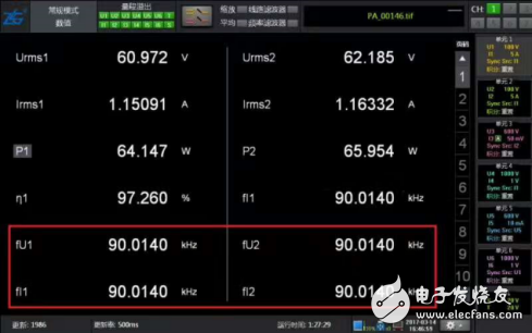
When testing wireless charging signals up to 90KHz, the voltage, current and power are very stable, which can provide strong data support for wireless charging efficiency calculation.

Figure 2 Wireless charging high frequency power measurement
The pin refers to the connection between the internal circuit of the integrated circuit (chip) and the peripheral circuit, and the pin constitutes the interface of the chip. According to the function, the pins of AT89S52 can be divided into four categories: main power supply, external crystal oscillator or oscillator, multi-function I/O port, and control, strobe and reset.
Terminal Pins,Terminal Hardware Pin,High Precision Terminal Pins,Terminal Pins For Pcb
Sichuan Xinlian electronic science and technology Company , https://www.sztmlch.com