Abstract: A fatigue driving detection device is developed for the current severe fatigue driving behavior. An infrared emitting diode and two infrared receiving heads are mounted on the front of the seat headrest facing the driver's head. The intensity of the infrared emission is controlled by the single chip microcomputer, and the relative position of the head can be detected by detecting the information of the receiving head. . If the driver is in a fatigue driving state, the head must deviate from the normal position and the time exceeds the set value, an alarm and brake control signal is output. The system was tested on several typical vehicles, which verified the correctness and effectiveness of the method and achieved high measurement accuracy.
This article refers to the address: http://
1 detector structure features
The detector is controlled by a single-chip controlled reflective infrared sensor to detect the position of the driver's head. By detecting the relative position of the driver's head in the normal sitting position and the headrest of the seat, it is automatically determined whether the driver is in a fatigue driving state. .
If the driver is in a fatigue driving state, the head must deviate from the normal position and the time exceeds the set value, an alarm and brake control signal is output. The reflective infrared sensor in the detector consists of an infrared emitting diode and two infrared receiving heads. The infrared emitting diode emits a modulated 38 kHz infrared beam, which is mounted on the headrest of the seat and facing the driver's head. The infrared emitting diode is placed in the middle, and two infrared receiving heads are symmetrically placed on the left and right sides.
2 Driver's head position analysis
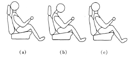
During driving, the driver's head position is different during normal and fatigue. The side view is shown in Figure 1. Figure 1 (a) shows the driver's head position and seat headrest when driving the car normally. A small distance of a few cm, rather than completely close the headrest, because driving the eyes against the headrest will feel very uncomfortable, it is not convenient to observe the road near the car.
Figure 1 (b) shows the driver's most common driving sleep posture when driving a car. It is also the driver's initial fatigue sleep posture. At this time, the driver's head is generally larger than 15 cm from the seat headrest. In this case, it should be timely. Alarm, if the brake lasts for 2 s, the brake system should be started automatically. However, other short-term non-fatigue actions, such as the switch on the instrument panel, and the short-time movements such as the back-to-head observation, also have similar distance changes. In this case, time can be used to distinguish the inoperative recovery of the normal position within 2 s.
Figure 1 (c) shows the driver's consciously short break and closed eyes driving, but not fully asleep, but this is a prelude to a complete sleep, with the head position close to the seat headrest, distance It is 0. In this case, it should be alarmed in time, and it will evolve into the situation of Figure 1 (b).

Figure 1 driver's head position side view
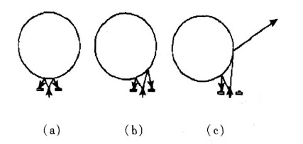
Figure 2 is a top view of the driver's head with a circle representing the driver's head and an arrow representing the path of infrared emission and reflection. Figure 2 (a) is a schematic diagram of the relative position of the driver's head and the infrared sensor during normal driving. The infrared rays are emitted from the middle infrared emitting diode to be reflected by the driver's head back to the left and right infrared receiving heads. equal.
Figure 2 (b) shows the position of the head after the driver's fatigue, which is skewed to the left or right. This is different from the typical position of Figure 1 (b). It is an intermediate transitional fatigue pattern and will eventually Transform to the position of Figure 1 (b), then the infrared sensor will detect different distances from left to right, and should also alarm or output the brake signal.
Figure 2 (c) shows the position where the head continues to shift after the driver fatigues. The infrared receiving head on one side can no longer receive the reflected infrared rays, and the result is infinitely large in the computer program. This shows the driver. The degree of fatigue is further enhanced, and the alarm signal should be alarmed or output in time.

Figure 2 Top view of the driver's head position
3 hardware design of the detector
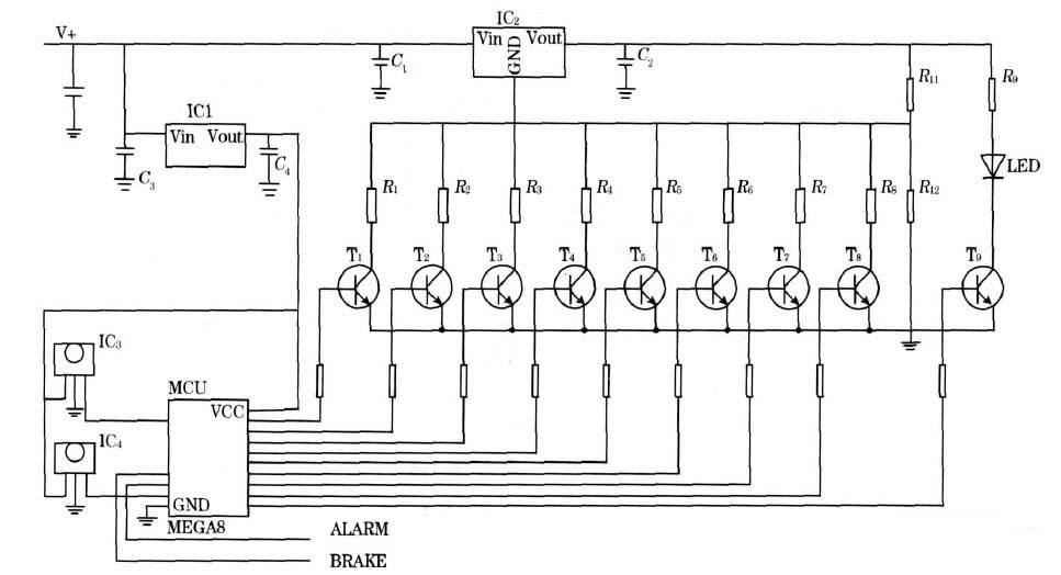
The hardware circuit diagram of the detector is shown in Figure 3. In the figure, the LED is an infrared emitting diode, IC3 and IC4 are infrared receiving heads, and the MCU is an ATMa8 microcontroller.

Figure 3 detector hardware circuit
The LED emits a 38 kHz infrared modulated beam that is reflected by the driver's head and then illuminates the receiving window of IC3 and IC4. IC3 and IC4 demodulate the received signal and send it to the high or low level after amplification. The input port line of the MCU of the single-chip microcomputer, the computer program sends the value of the line line to the memory for storage, and the later program is used as a judgment basis.
The effective detection distance of the infrared light emitted by the infrared emitting diode LED corresponds to the current passing through the infrared emitting diode. The current of the infrared emitting diode LED is determined by the output voltage of the three-terminal integrated voltage regulator IC2, and the output of the three-terminal integrated voltage regulator IC2 is integrated. The voltage is controlled by the control word output by the computer program.
The maximum value of the control word is binary 11111111d. At this time, all the R1 to R8 are grounded, the integrated resistance of R12 is the smallest, the output voltage Vout of the three-terminal integrated regulator IC2 is also the smallest, and the effective distance of the infrared beam emitted by the LED is also the smallest. The values ​​of R1 to R8 can adjust the effective distance of the infrared beam emitted by the LED to about 1 cm. When the minimum value of the control word is binary 00000000d, the R1 to R8 resistors are all suspended, the integrated resistance of R12 is R12, the output voltage Vout of the three-terminal integrated regulator IC2 is the largest, and the infrared beam emitted by the infrared emitting diode LED is effective. The distance is also the largest, and the value of R12 can be appropriately adjusted to adjust the effective distance of the infrared beam emitted from the infrared emitting diode LED to about 20 cm. An effective detection distance of 1 to 20 cm can meet the actual needs.
4 detector software design
4. 1 distance detection method
The effective distance detection corresponds to the control word sent by the single-chip microcomputer. The distance detection method is: gradually reducing the intensity of the infrared emission until the reflected infrared beam is not received, and the distance value corresponding to the control word at this time is the current driver's head and The distance from the seat headrest.
4. 2 Automatic calibration of the driver's head position
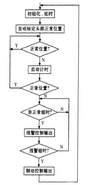
The block diagram of the MCU is shown in Figure 4. The program that automatically calibrates the normal position of the head runs for a period of time after the car starts the engine, because fatigue driving does not occur during this time. When driving to the main road, the movement of the head is gradually stabilized. This is the right time to normalize the position of the head. Each time it is recalibrated because the driver may change, the position of each person's head is not exactly the same, and the results of the calibration will be different.

Figure 4 Automatic calibration block diagram of the normal position of the head
The procedure for automatically calibrating the normal position of the head is to gradually reduce the current intensity of the infrared emitting diode from strong to weak, and simultaneously detect the output state of IC3 and IC4 to determine whether it has reached the critical point that is not received. Small limits, while reading the value of the control word at the moment as a distance calibration. When the signal levels output by the two left and right infrared receiving heads IC3 and IC4 are the same and can be kept for a certain period of time, the control word at this time can be used as the standard distance calibration. Each control word corresponds to 1 actual distance.
4. 3 Detection of the driver's head deviating from the normal position
If an infrared receiving head does not receive the infrared signal, it is determined that the distance between the infrared receiving head and the driver's head is greater than the distance associated with the control word at this time.
The information output by the two infrared receiving heads reflects the distance between the driver's head and the two infrared receiving heads at the same time. Compared with the standard distance, the driver's head can be judged to be normal or forward tilt, roll, and rear. Yang. Whether the output alarm and brake control levels are determined by the computer program depends on the duration of the driver's head deviating from the normal position.
5 Analysis of experimental results
The detector was installed on a car such as Jetta and Swift and a large number of experiments were carried out to test the normal driving state and fatigue driving state of the five drivers. The test data is shown in Table 1. It can be seen that the detector can track and judge the fatigue state of the tester in real time, and also plays a warning role for the improper sitting posture of drunk driving.

6 Conclusion
The detector completes the recognition of the normal position of the driver's head, and then determines whether the driver is fatigued or not. It is an intelligent application of simple technology. The detector can equip existing vehicles at low cost, improve the probability of safety, and facilitate large-scale promotion, and the market demand potential is huge.
LED wall washers are high
power LED lights that are used for decorative lighting and highlight, or wash
walls, of buildings, clubs, hotels, stages, parks, plazas, commercial building
facades, art galleries, etc., with different kind of colors.
The LED wall washer can even change their colors while projecting. The RGB LED
wall washer lights can project various colors and change the color by
programming the LED wall washer the way you want to. LED wall washers can be
used for clubs, stages, parks, plazas, commercial building, art gallery,
landscape, architectural decoration, etc.
Indoor Wall Washer,Led Christmas Wall Washer,Led Light Wall Washer,Led Outdoor Wall Washer
ZHONGSHAN G-LIGHTS LIGHTING CO., LTD. , https://www.glightsled.com