The programmable controllers produced by SIEMENS in Germany are also widely used in China, and are used in metallurgy, chemical and printing production lines. Siemens (SIEMENS) PLC products include LOGO, S7-200, S7-1200, S7-300, S7-400 and so on. Siemens S7 series PLC is small in size, fast in speed and standardized, with network communication capability, stronger function and high reliability. S7 series PLC products can be divided into micro PLC (such as S7-200), PLC with small-scale performance requirements (such as S7-300) and PLC with medium and high performance requirements (such as S7-400).
Siemens plc working principle:When the PLC is put into operation, its working process is generally divided into three stages, namely, input sampling, user program execution and output refresh. Completing the above three phases is called a scan cycle. During the entire operation, the CPU of the PLC repeatedly executes the above three stages at a certain scanning speed.
Input sampling
During the input sampling phase, the PLC reads all input states and data in a scan mode and stores them in the corresponding cells in the I/O map area. After the input sampling is finished, it is transferred to the user program execution and output refresh phase. In these two phases, the status and data of the corresponding unit in the I/O map area does not change even if the input status and data change. Therefore, if the input is a pulse signal, the width of the pulse signal must be greater than one scan period to ensure that the input can be read in any case.
User program execution
During the user program execution phase, the PLC always scans the user program (ladder) in order from top to bottom. When scanning each ladder diagram, the control lines formed by the contacts on the left side of the ladder diagram are always scanned first, and the control lines composed of the contacts are logically operated in the order of first left, then right, first up and then down. And then refreshing the state of the corresponding bit of the logic coil in the system RAM storage area according to the result of the logic operation; or refreshing the state of the corresponding bit of the output coil in the I/O map area; or determining whether to execute the ladder diagram The specified special function instructions.
That is, during the execution of the user program, only the state and data of the input point in the I/O map area will not change, while other output points and soft devices are in the I/O map area or the system RAM storage area. The status and data are subject to change, and the ladder diagrams listed above, the program execution results will work on the ladder diagrams that use these coils or data; instead, the ladder diagrams below, The state or data of the refreshed logic coil can only be applied to the program that is listed above in the next scan cycle.
Output refresh
When the scanning user program ends, the PLC enters the output refresh phase. During this time, the CPU refreshes all the output latch circuits according to the corresponding state and data in the I/O map area, and drives the corresponding peripherals through the output circuit. At this time, it is the real output of the PLC.
The same several ladder diagrams are arranged in different order and the results are different. In addition, the results of the operation of the scanning user program are different from the results of the parallel operation of the hard logic of the relay control device. Of course, if the time taken by the scan cycle is negligible for the entire run, there is no difference between the two.
Siemens plc programming tutorialFor many friends who have not used S7-200PLC, many problems may become a hindrance to everyone, and it is difficult to get started. The following is an example to introduce you to the first step when using the S7-200PLC, to help you take the first step in using the PLC. The function that I hope to achieve in this paper is to press a switch to light an output point. This article can help you solve the following problems when using the S7-200 for the first time:
(1) What hardware and software do you need to prepare?
(2) How to wire the PLC?
(3) How to communicate with PLC?
(d) How to write a program?
(5) How to debug the PLC?
Tools/raw materials
Computer with V4.0 STEP 7 MicroWIN programming software
One PPI programming cable
One Siemens S7 200 CPU
Method / step
1(1) What hardware and software do you need to prepare?
When using the S7-200 for the first time, you need to prepare the hardware: S7-200 CPU, such as CPU224XP (order number: 6ES7
214-2BD23-0XB8)
CPU224XP
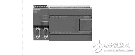
2 programming cable PC/PPI cable (order no.: 6ES7 901-3DB30-0XA0)
USB PC/PPI cable
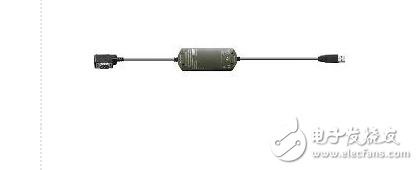
3 software to be prepared: SETP7-Micro/Win V4.0 SP6
Also need to prepare a computer with Windows XP SP2
With the hardware in place, we need to properly install the S7-200 programming software on the computer. Special Note Please note that this software is SETP7-Micro/Win, not SETP7. According to the old engineer, SETP7 is used for programming series S7-300 PLC, and can't program S7-200. For the SETP7-Micro/Win software, the currently used version is V4..0 SP6. As with other software, once you have properly installed the programming software, you will see the icon shown below on your desktop. At this point, we are ready for the next step of debugging!
STEP7-Micro/win icon

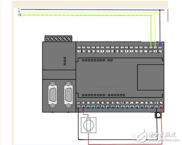
4 (2) How to wire the PLC?
As you can see from the wiring diagram below, all we need to do is provide power to the PLC and positive for the digital inputs.
Make sure the wiring.
5 (3) How to communicate with PLC?
1. Connect the programming cable
Plug the USB port side of the programming cable into the computer and the DB interface into the PORT0 or PORT1 of the PLC. Then
The PLC mode switch is set to STOP.
2. Programming software settings
(1) After opening the programming software, on the left side of the entire interface, click to set the PG/PC interface. As shown below:
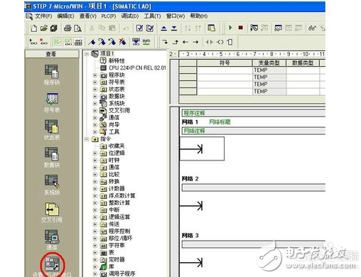
6 In the dialog that appears, select PC/PPIcable (PPI) and click on Properties.
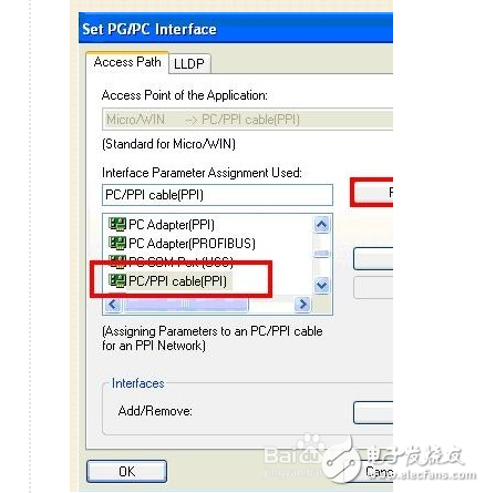
7 The first interface of the Properties dialog box, use the following settings: In the second tab of the Properties dialog box, select the communication interface as USB, as follows:
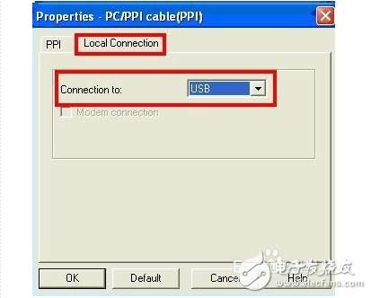
After 8 save and close the corresponding dialog.
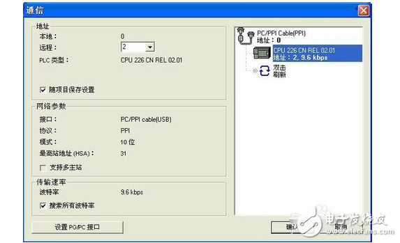
(2) Return to the initial interface of the programming software, and then click on the communication.
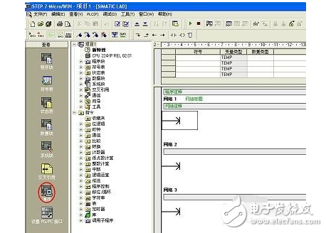
9 The following interface appears:
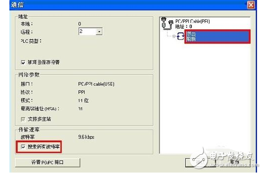
After checking all baud rates, double-click to refresh.
If the following page can appear, it means that the communication between the PC and the PLC is successful.
(d) How to write a program?
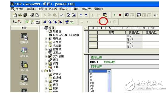
Open the programming interface and click on the red mark to add a normally open contact.
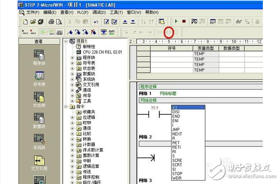
The same method adds an output coil
You need to assign the correct address to the input and output as shown below. Then click to download
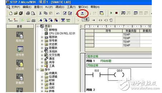
After the following interface appears, continue to click download
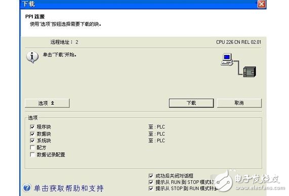
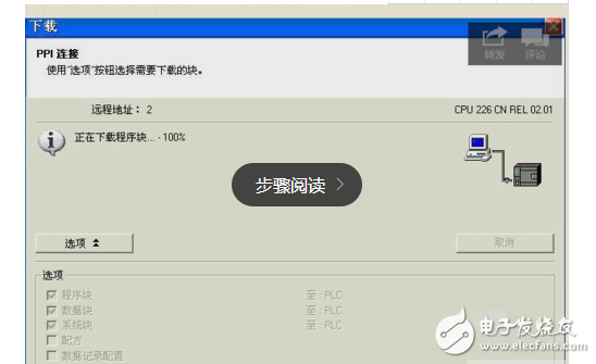
The following image shows the interface in the download:
After the download is successful, you can perform PLC debugging to further test whether the specific functions can be implemented.
5) How to debug the PLC?
First set the mode switch to RUN, then toggle the switch on the input point I0.0 to see the output point.
Bright. At this point, it shows that our program and PLC are running normally.
If you want to monitor the status of the input and output points on the programming software, you can click on the status table.
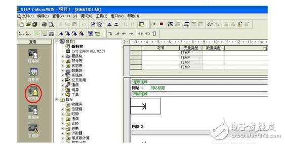
After opening the status table, enter the address you want to monitor in the address bar as follows:

Then click on the monitor:

After normal monitoring, you can see the corresponding value in the current value:

20 when the switch is not pressed

21 to complete the entire operation process
GPS Tracker, Locator for Precious Assets.
Features that already exist
âš« Tracking: It sends GPS (Location, speed) and sensors (if any) information to your application server with configurable report interval (moving or stationary).
âš« Geofence: It supports circle and polygon setting.
âš« Backup Battery (optional): With a backup battery (300mAh), the device sends a tamper message if the main power supply harness is disconnected.
âš« 3-Axis Accelerometer: With a built-in 3-axis accelerometer, the device can detect trip start/trip end, and to report harsh braking, harsh acceleration, and impact.
âš« Storing Message: The device stores up to hundreds of messages while there is no GSM signal.
âš« Low Voltage Detection (optional): Device switches to deep sleep mode if supply voltage drops below a threshold.
âš« Power Saving Mode: Device periodically wakes up and sleeps when vehicle engine is OFF.
âš« OTA (Over the Air): The device`s firmware can be upgraded via TCP.
âš« Waterproof Case: IPX65 waterproof
âš« Bluetooth-positioning: It will support bluetooth feature for positioning.
âš« Mileage: Reports trip start, trip end and the mileage.
âš« Moving Wakeup: Device will automatically wakeup when it senses moving of the asset and power down itself when it is stationâš« Drop Alarm: Using embedded light sensor to detect the drop/detach from the tracking object.
âš« Cell-ID Based Location: Device reports cell-ID based location information where
âš« Flexible battery selection
Other functions can be customized.
Asset GPS Trackers,Wireless GPS Trackers,4G asset GPS trackers,LTE asset GPS Trackers,Waterproof GPS Trackers
eSky wireless Inc , https://www.eskygpsiot.com