1 SD card standard SD card standard is a standard designed and licensed by the SD Card Association for removable storage devices. It is mainly used to formulate the card's external dimensions, electrical interfaces and communication protocols.
1.1 SD card pin function The appearance of the SD card is shown in Figure 1. The pin functions are listed in Table 1. The SD card's pins have dual functions and can operate in either SD mode or SPI mode. The function of the pins is different in different modes.
This article refers to the address: http://
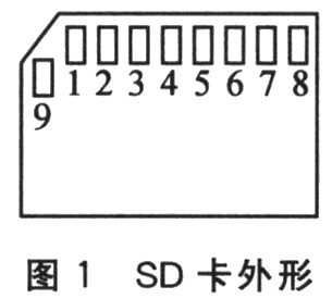
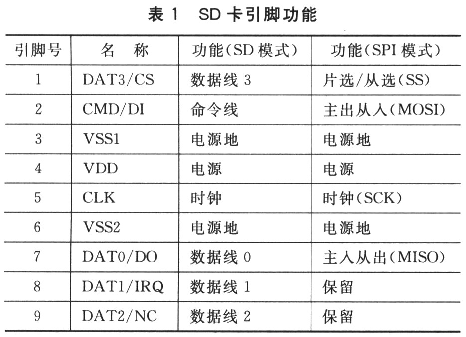
The SD mode is mostly used in applications where the SD card read/write speed is high. The SPI mode is based on sacrificing read and write speeds for better hardware interface compatibility. Since the SPI protocol is currently a popular communication protocol, most high-performance microcontrollers are equipped with an SPI hardware interface, and the hardware connection is relatively simple. Therefore, in the case where the SD card read/write speed is not high, the SPI mode is undoubtedly a A good choice.
1.2 SPI Mode SPI mode is a simple command response protocol. After the main controller issues a command, the SD card returns a corresponding response for a command that is not the same as S.
The command list of the SD card starts with CMD and ACMD, and refers to the general command and the dedicated command respectively, followed by the number of the command. For example, CMD17 is a generic command used to read a single block of data.
In SPI mode, commands are sent in the following 6 bytes:

Each frame of the command begins with "01", followed by a 6-bit command number and a 4-byte parameter (high-order first, low-order first), and finally 7-bit CRC checksum and 1-bit stop bit "1".
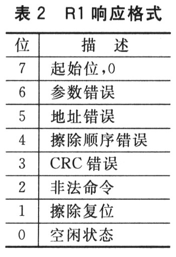
Each command of the SD card will return the corresponding response type. In SPI mode, there are three types of responses: R1, R2, and R3, which occupy 1, 2, and 3 bytes, respectively. Only the format of the R1 response is listed here, as listed in Table 2. When the status described in the table appears, the corresponding position is 1. The first byte format of R2 and R3 is exactly the same as R1. For details, please refer to the SD card standard.
2 hardware design This design uses Freescale's 32-bit low-power microcontroller MCF51QE128, using SPI mode to achieve interface with the SD card.
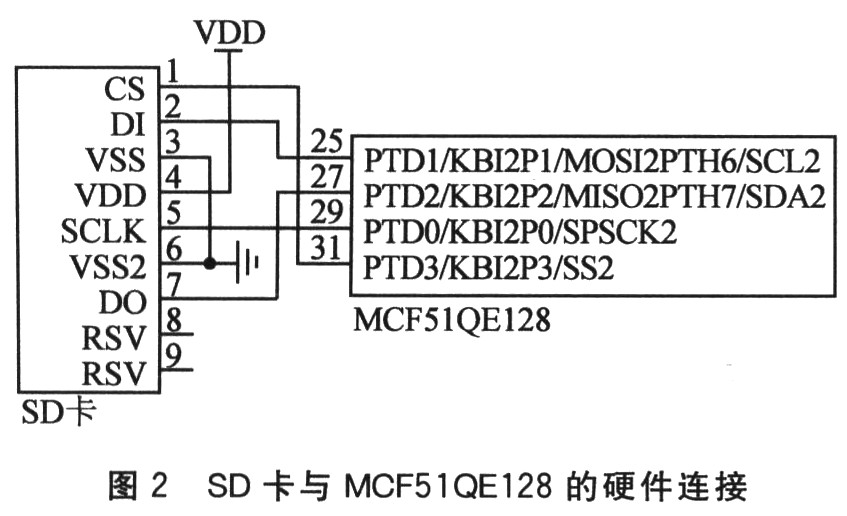
Because the MCF51QE128 is a low-power microcontroller, the operating voltage is typically 3.6 V, which is compatible with the operating voltage of the SD card, so it can be directly connected to the SD card without the need for a level shifting circuit. The second SPI port of the MCF51 QE128 is used here, and the hardware connection is shown in Figure 2.
3 software implementation software part mainly realizes the initialization of MCF51QE128, the underlying SPI communication, and the general write command, initialization and single-block data reading and writing of SD card.
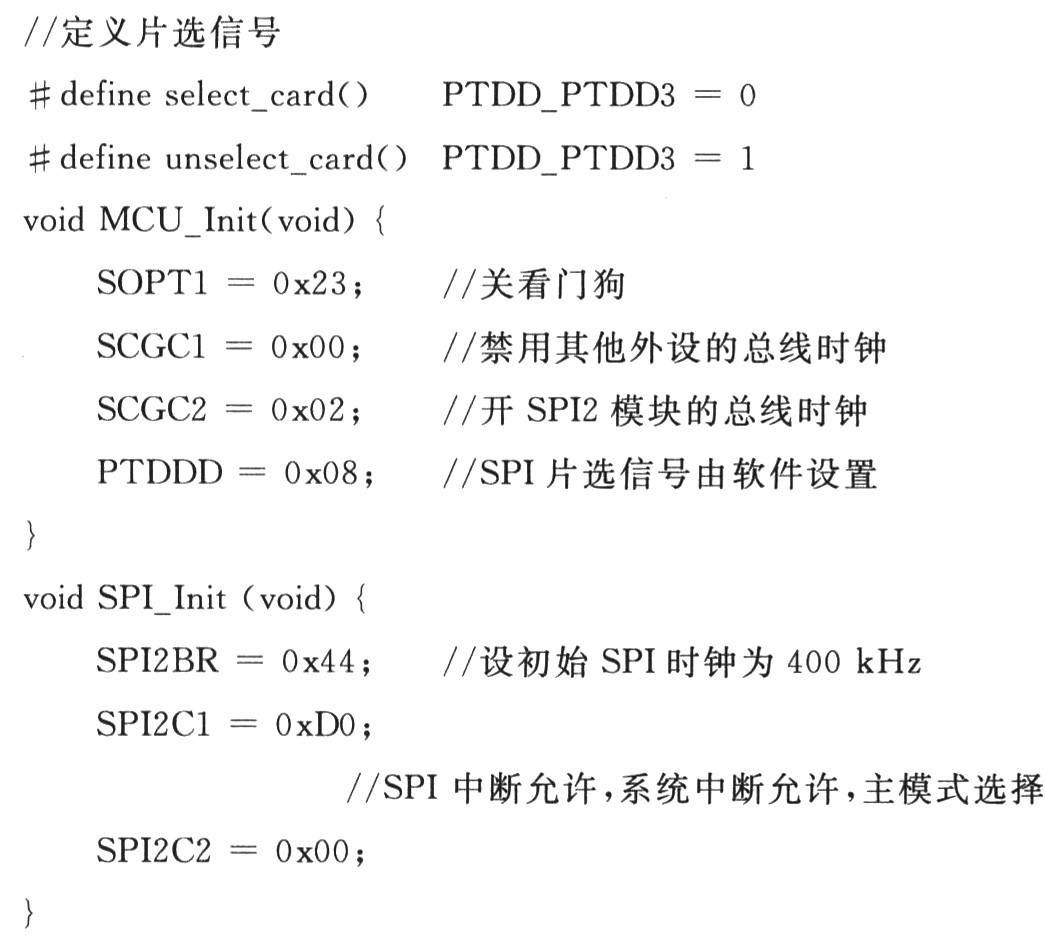
3.1 Initialization of MCF51QE128 Before communicating with the SD card, you first need to configure the MCF51QE128 and initialize the SPI port. code show as below:
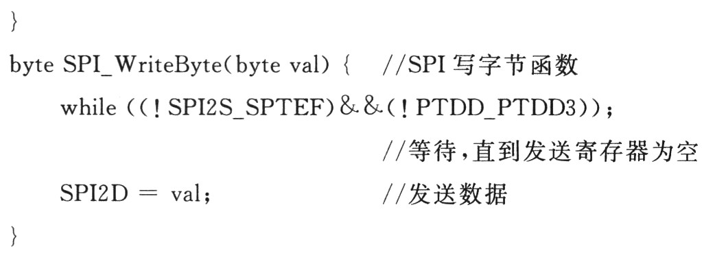
3.2 The underlying SPI communication of the underlying SPI communication is the key to achieving final read and write. Since the MCF51QE128 has its own SPI hardware interface, it only needs to read and write the value of the SPI data register. Here, three data types of byte, word, and dword are customized, which correspond to 8-bit, 16-bit, and 32-bit data, respectively. code show as below:

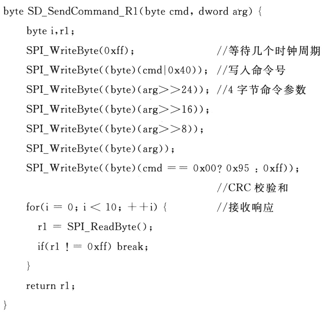
3.3 General Write Commands for SD Cards Since the commands of the SD card have a uniform format, a common write command function can be used to implement the transmission of all commands. In addition, considering that the response type of most commands is R1, the response type received by the general write command function here defaults to R1. The function code is as follows:
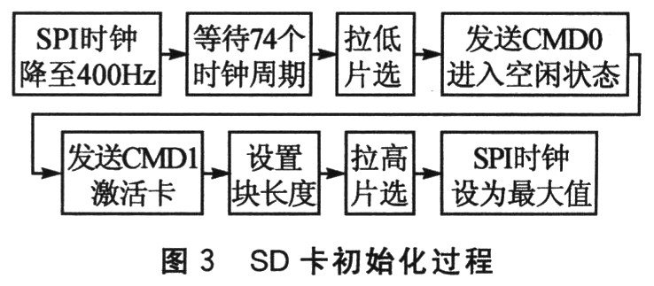
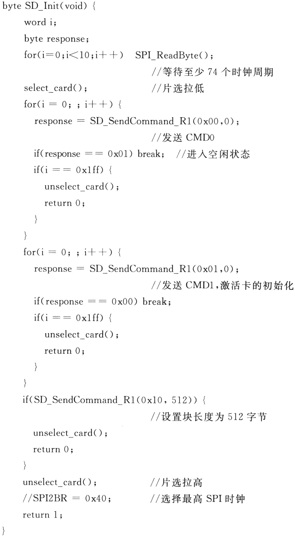
3.4 Initialization of the SD Card The initialization of the SD card must follow certain steps. First reduce the SPI clock to 400 kHz and wait for at least 74 clock cycles. Then pull down the chip select signal and send the CMD0 command to reset the SD card and put it into SPI mode. Here you need the correct CRC check, the check byte is 0x95. If the SD card enters the idle state (that is, when the receiving response is 0x01), the CMD1 command is sent to activate the card initialization process, and the response is 0x00. Then set the length of the block, typically 512 bytes. Finally, the chip select is pulled high and the SPI clock is set to the maximum value to ensure maximum read and write speed. The SD card initialization process is shown in Figure 3.
The SD card initialization code is as follows:
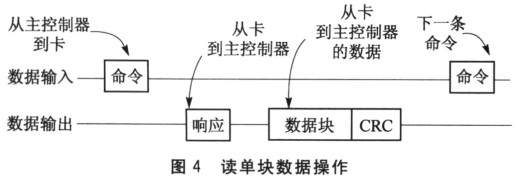
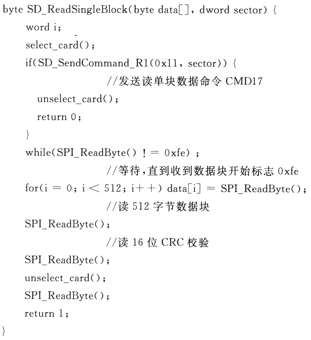
3.5 SD card single block data read and write SPI mode supports single and multiple block data read and write operations, can be achieved by sending the corresponding command. The operation process of reading a single block of data is shown in FIG. After the chip select is pulled down, the read single block data command CMD17 is first sent by the main controller MCF51QE128, and then waits for the response of the SD card. When the data block start flag 0xfe is received, 512-byte data is read from the SD card, and the 2-byte CRC check bit is finally read.
The function code for reading single block data is as follows:
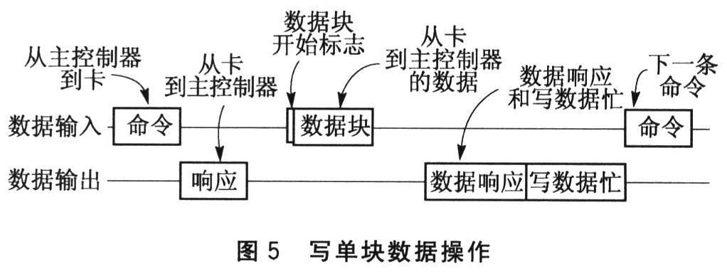
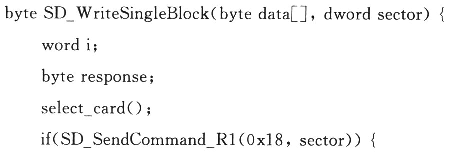
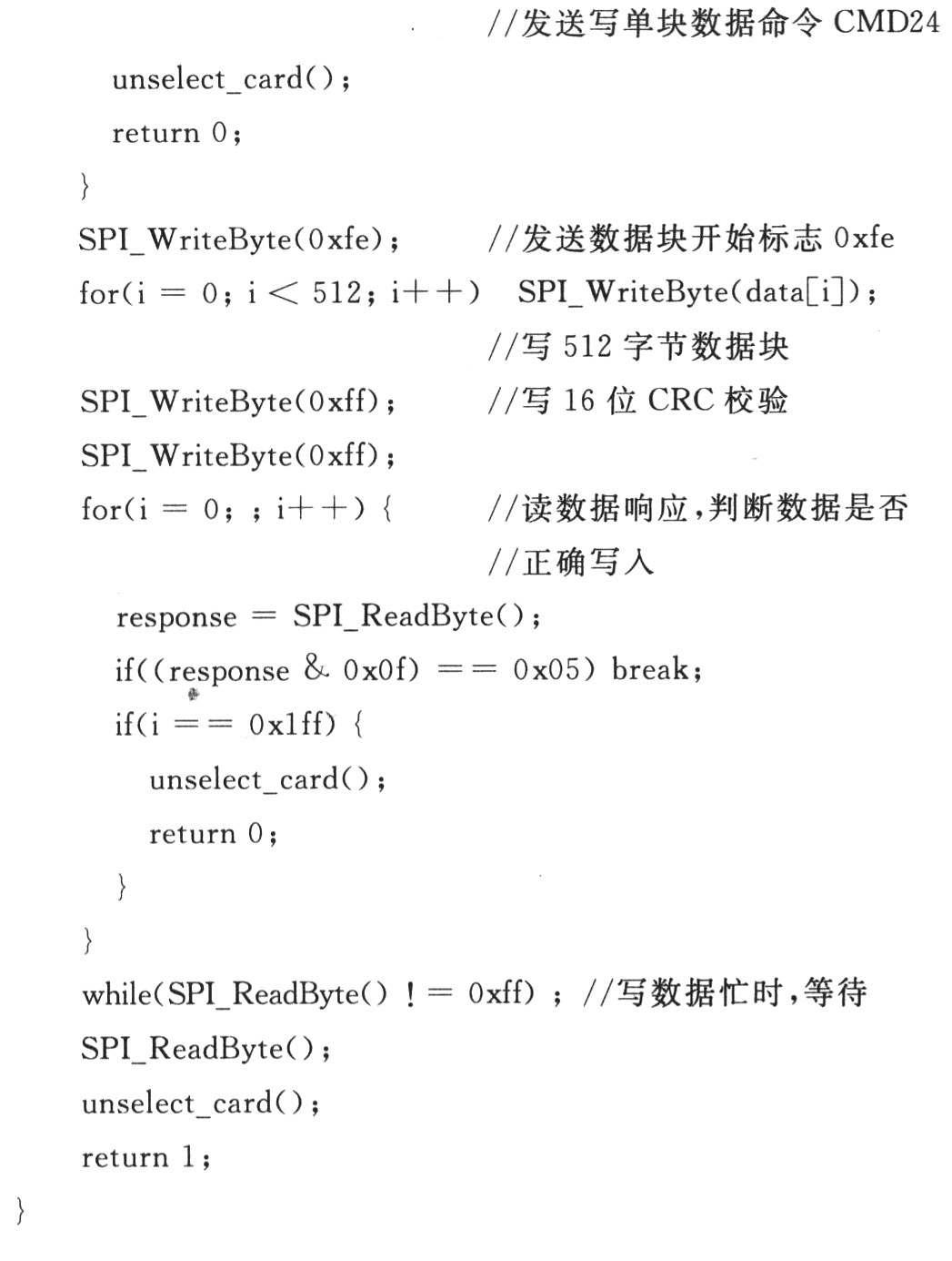
The operation of writing a single block of data is similar to the read operation, as shown in Figure 5. After the low chip is selected, the write single block data command CMD24 is also sent by the main controller MCF51QE128. After the SD card responds correctly, the data block start flag 0xfe is transmitted, and then the 512 byte data block and the 2-byte CRC check are transmitted.
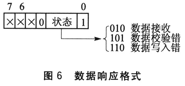
After writing the data, the SD card will send a 1-byte data response to feed back the data write. The format is shown in Figure 6. When the data is correctly written to the SD card, the data response is 0x05. Finally, read the data bus and wait while the write data is busy until the bus is high.
The function code for writing a single block of data is as follows:
Conclusion <br> SD card is a widely used erasable mass storage device, and its interface design can be used as a general solution for storage units in various embedded systems. This paper combines the relevant technology of SD card standard, based on MCF51QE128 microcontroller to complete the hardware interface and the design of the underlying communication software. On this basis, the file system can be further constructed to achieve more efficient management of stored data.
Flash Ring Light,Ring Light Rgb,Camera Led Ring Light,Selfie Led Ring Flash Light
SHAOXING COLORBEE PLASTIC CO.,LTD , https://www.colorbeephoto.com