With the development of electronic technology and the emergence of digital audio sources, people's eyes are mostly focused on CD.VCD.DVD and MP3 that have been popular in recent years. Is TAPE outdated? The fact is not the case. Although the butterfly machine has the advantages of fast selection of songs, beautiful sound quality, and large dynamic range, it also has its own shortcomings, such as the digital smell that is difficult to eliminate, and from the current situation, there are no or few admission functions on the market. , (In addition to MD), and the tape drive can just make up for the shortcomings of the light butterfly, and its unique soft sound quality, so that audio fans who are accustomed to digital sound feel a different flavor, in fact, the world famous electronic manufacturers For example, Sony, Panasonic, etc. have always launched new tape audio-visual products.
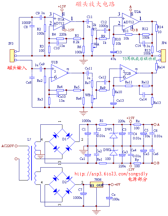
The following is a preamplifier circuit made by AD712 made by the author:
The principle is briefly described as follows. U1 is the head amplification part, in which C8 and the head coil form a resonant circuit to improve the high-frequency component. The capacitor uses a ceramic dielectric capacitor or a CBB capacitor, and U2 is a linear amplification part, in which high and low bass compensation is added Taste the circuit, so that you can directly push the ordinary low-impedance headphones at the output, eliminating the tone part and tone adjustment circuit, so that it can also be used as a part of the audio source and then connected to the power amplifier circuit. In addition, this circuit also separately designed a regulated DC power supply circuit to provide power for the motor on the movement. Readers can increase or decrease the output DC voltage according to the actual situation. (Add a diode to the periphery of the three-terminal regulator integrated block Method, you can refer to the relevant books)
From the actual use, the effect is good. It can sweep the sound quality of the ordinary commercially available recorders and the domestic player's monotone ambiguity. Some inaudible details are also expressed. From the perspective of the production process, in order to ensure The balance of the channel should be strictly selected, especially to ensure the consistency of the two groups of devices. As shown in the figure below, R3, R4, R5, C10 and other no components, it is best to use a digital multimeter to test, the small capacity capacitor is selected as CBB, Or use a fever grade, a metal film for resistance, in order to minimize noise, this production has easy to succeed, strong practicality. 
In addition, in order to obtain a better listening effect, the selection of the front-level head is also particularly important. Generally, the DM62 head is used. You can use your existing domestic sound follower, directly connect the head of the head with a shielded wire, and use it You can also buy a ready-made domestic tape movement on the market, usually with a 9V or 12V electronic speed control motor (there is a small hole on the back to adjust the head speed with a screwdriver) directly Just connect the power supply, and then connect the head amplifier board with a shielded cable, and you can add a self-made headphone amplifier or power amplifier circuit to the back. A complete DIY audio work is completed.
Precautions for production and installation:
1. Because the head amplifier circuit belongs to the pre-stage voltage amplification, its magnification is large, and it is easy to be interfered in the AC magnetic field, so it should be as far away from the transformer as possible during installation, and you can adjust the direction of the transformer to make the interference At least, or simply shield it with metal, once and for all.
2. It is also very important to pay attention to the grounding of the movement. It is very simple, as long as a wire is welded from the movement to the grounding foot of the power filter of this circuit board. Use shielded wire for the signal wire used to connect the magnetic head.
3. When the sound test is done after connecting the wiring, the orientation of the magnetic head should also be adjusted to achieve the best sound quality. The following is the electrical schematic of the board and the physical picture
.
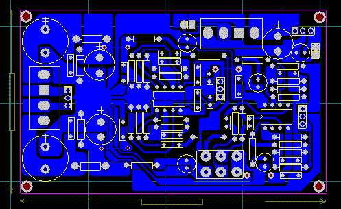
The PCB diagram is as follows: (size 10CM X 6CM) 
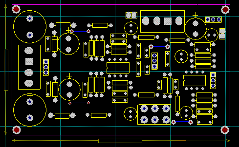
The component layout diagram is as follows

The printed circuit board is as follows


Follow WeChat

Download Audiophile APP

Follow the audiophile class
related suggestion
![[Photo] High-fidelity FM audio signal transmission circuit](http://i.bosscdn.com/blog/20/06/41/5205835846.gif)