Automobile testing is an important means to discover various problems in the design and development of automobiles. Based on the test results, it can make an objective evaluation of various performances of automobiles. As one of the basic projects of the automotive industry, automotive testing has played an important role in the overall development of the automotive industry. The automotive performance test system is a key component of the automotive test project. It is composed of several interconnected and interacting sensors and instruments. It is an organic whole composed of tests for the performance of the car. The performance of the automotive test system. It often has a major impact on the effectiveness of the entire vehicle test.
Overall structural design of the system
The automotive test mainly includes test items such as power performance, fuel economy, steering stability and emission characteristics. The main performance parameters include speed, acceleration, fuel consumption, temperature, and dynamic motion parameters in the steering stability test. The test signals of these parameters are processed into the C805l-F020 microprocessor after being processed (shaping, filtering, amplifying, etc.) by the front-end processing module, and the connection to the Zigbee terminal node is realized through the serial port after performing analog-to-digital conversion and data processing inside the single-chip microcomputer. Then, the terminal node sends the data in the WLAN, and the Zi-gbee central node receives the data and communicates with the host computer through the serial port. The central node can also send the command of the upper computer to the terminal node to control the terminal node to execute. The overall structure of the system is shown in Figure 1.

Front-end processing module
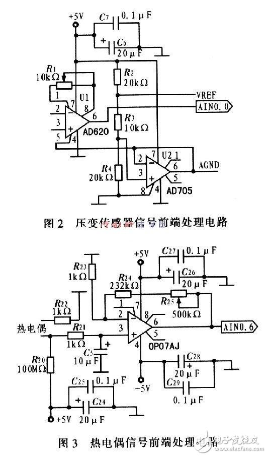
The sensor converts various common non-electricity signals into power signals, which are generally weak. The front-end processing module processes these signals and sends them to the A/D conversion port of the microcontroller. The system has a total of 8 sensor signals, including 2 voltage-variable sensor signals, 2 -5 ~ +5 V voltage signals, 2 4 ~ 20 mA current signals and 2 front-end processing of thermocouple signals. The front-end processing hardware circuits of the pressure-variable sensor signal and the thermocouple signal are shown in FIG. 2 and FIG. 3, respectively.

The AD620 is a low-cost, high-precision instrumentation amplifier that requires only one external resistor to set the gain with a gain range of 1 to 10,000. The front-end processing of the pressure-variable sensor signal uses an amplifier circuit composed of AD62-0 and AD705. This part is powered by a single power supply. The AD705 is a voltage follower that provides the zero point of the output voltage for the AD620. Send VREF, AGND to the AINl of the 8-bit precision AD-Cl of the MCU. 0, AINl. 1 port, using the software program to achieve the reference voltage of the road signal and the calculation of the analog ground. The thermocouple sensor is used to measure the temperature of key components of the car. The front-end processing circuit uses the adjustable gain amplifier circuit of OP07. OP07 is a low noise, non-chopper-stabilized bipolar op amp IC with very low input offset voltage. Low offset and high open loop gain make OP07 especially suitable for high gain measurement equipment and amplification sensors. Weak signal, etc. In the case where the accuracy is not high, the offset voltage of OP07 can be neglected. In this circuit, R25 and R24 are used to adjust the system amplification factor. When different types of thermocouples are selected, the resistance values ​​of the two can be adjusted appropriately.
Watch frame,Watch shell,Watch cover,watch roll case
Dongguan Yingxin Technology Co., Ltd. , http://www.yingxinelectronic.com