How to design a miniaturized ultra-thin high signal-to-noise ratio electret microphone (ECM)
At present, the market demand for microphone products below Φ4mm and thickness below 1.5mm is gradually increasing. While miniaturization of devices is required, the requirements for sensitivity and signal-to-noise ratio have increased. This has a greater impact on the design and production of microphones, and it needs to be optimized to achieve all aspects of ECM.
The ECM signal-to-noise ratio is composed of two aspects, sensitivity (corresponding to the size of the signal) and output noise (corresponding to the size of the noise). Sensitivity is composed of acoustic sensitivity and circuit gain. Among them, acoustic sensitivity is related to ECM's diaphragm area, diaphragm tension, plate spacing, polarization potential, and back cavity volume; circuit gain is related to the parasitic capacitance of the lead, amplifier gain, and amplifier parasitic capacitance. The output noise is also mainly composed of two aspects: acoustic noise and electrical noise: acoustic noise is related to the plate spacing, plate tension, plate area and back cavity volume; electrical noise is related to amplifier gain and amplifier noise.
This article will mainly discuss the impact on the ECM signal-to-noise ratio from the two aspects of acoustic design and circuit design; and give specific design examples.
Acoustic design affecting ECM signal-to-noise ratio
In the microphone design, the design parameters related to the acoustic characteristics include the area of ​​the diaphragm, the tension of the diaphragm, the distance between the plates, the polarization potential, and the volume of the back cavity. Among them, in a specific microphone target product, when the gasket width is fixed, the diaphragm area is basically fixed; in addition, for products with a certain height, the back cavity acoustic volume is also basically fixed. In this way, in the ECM design, the optimal adjustment of the product can only be carried out from the aspects of diaphragm tension, gasket thickness (polar plate spacing), and selection of polarization potential.
In the microphone design, the parameters of diaphragm tension, spacer thickness, and polarization potential influence each other and restrict each other. In order to get the best microphone design, it is necessary to make an appropriate compromise in their selection range. To do this, you first need to clearly understand the relationship between the parameters.
Figure 1 shows the relationship between the maximum polarization potential of the diaphragm and the distance between the plates under the condition that the diaphragm is not attracted. In an ideal state, the pull-in voltage of the polar plate (the potential difference between the diaphragm and the back polar plate) is proportional to the 1.5th power of the polar plate spacing. In order to ensure that the diaphragm does not pull in during the processing and in specific applications, it is necessary to ensure that the maximum potential appearing on the diaphragm is less than 2/3 of the pull-in voltage. After aging, the polarization potential will further decrease and tend to stabilize.
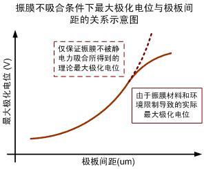
Figure 1 The effect of the spacing of the polar plates on the maximum polarization potential of the microphone
Figure 2 shows the effect of the volume of the back cavity on the microphone noise. In a miniaturized microphone, in general, when the back cavity is large (for example, a 4015 microphone), the acoustic noise is much smaller than the circuit noise. Therefore, acoustic noise accounts for only a very small part of the output noise, and the main output noise is dominated by circuit noise. However, as the microphone becomes thinner and thinner, the volume of the back cavity decreases rapidly, and the proportion of acoustic noise in the microphone output noise also increases rapidly. For example, in a typical 3013 microphone, the back cavity volume is only 1/6 to 1/4 of the 4015 microphone.
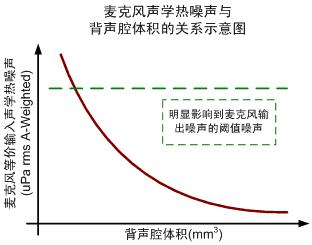
Figure 2 The effect of the volume of the back cavity on the microphone noise
Figure 3 shows the schematic diagram of the relationship between the diaphragm tension and the resonance frequency and sensitivity. Generally speaking, the resonance frequency is inversely proportional to the area of ​​the diaphragm and directly proportional to the square root of the tension of the diaphragm. The sensitivity is inversely proportional to the diaphragm tension. At the same time, as the diaphragm tension increases, the maximum polarization potential also increases.
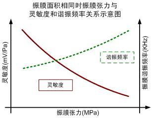
Figure 3 The effect of diaphragm tension on resonance frequency and microphone sensitivity
Figure 4 shows the relationship between plate spacing on sensitivity and harmonic distortion. When the polarization potential of the microphone is the same, the sensitivity is inversely proportional to the plate spacing. However, when the distance between the plates is reduced, the second harmonic introduced due to the nonlinear relationship between the capacitance and the sound pressure rises rapidly, resulting in the deterioration of the harmonic distortion characteristics.
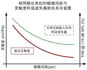
Figure 4 The effect of diaphragm tension on resonance frequency and microphone sensitivity
Figure 5 shows the preferred range of distance from the microphone pole plate assuming a certain polarization potential and diaphragm tension. It can be seen from the figure that, assuming that the polarization potential of the diaphragm is constant, then the optimal design value of the electrode plate spacing with the maximum signal-to-noise ratio as the optimization target decreases as the microphone size decreases. However, if it is assumed that the polarization potential and the distance between the plates are unchanged, then the optimal design value of the diaphragm tension with the maximum signal-to-noise ratio as the optimization target will increase as the microphone size decreases.
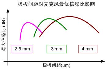
Figure 5 Assuming the preferred range of the distance from the microphone pole plate when the polarization potential and diaphragm tension are constant
Due to the mutual influence of various acoustic design parameters of the microphone, and at the same time limited by the microphone size, diaphragm material, reliability, cost, mass production yield rate, etc., in the actual engineering production, we must get an optimization The design requires a lot of engineering practice and a certain theoretical guidance. For a particular product, the range of possible changes in acoustic parameters is very limited. Therefore, in the design of modern electret microphones, many times, a better electrical design will be used to obtain a larger acoustic optimization range, thereby obtaining better product performance.
Electrical design that affects the signal-to-noise ratio of ECM
ECM equivalent circuit
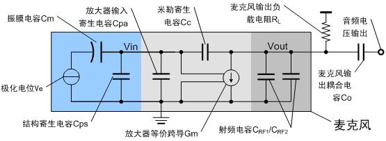
Figure 6 The internal circuit equivalent of the microphone and the external interface circuit
Figure 6 shows the equivalent circuit diagram of the microphone internal circuit and the interface circuit outside the microphone formed by the output load resistance RL and the output coupling capacitor Co.
The blue part marks the electrical parameters related to the microphone acoustic design. Among them, Ve is the polarization potential of the microphone, that is, the potential difference between the diaphragm and the back pole after the microphone passes through the polarization and aging process. The diaphragm capacitance is the capacitance between the diaphragm and the back plate. The structure parasitic capacitance Cps refers to the sum of the parasitic capacitance of the conductor part connected to the input pin of the amplifier due to the back plate, copper ring, pcb lead, etc. to the ground (case).
The light gray part marks the electrical parameters related to the microphone interface amplifier (eg JFET). Where Cpa is the input capacitance of the amplifier; Cc is the Miller parasitic capacitance, which is composed of the sum of two parts of the parasitic capacitance: the parasitic capacitance between the input and output pins of the amplifier, and the conductor part connected to the amplifier input pin in the microphone and the microphone The calculated capacitance of the conductor part on the output pin; Gm is the equivalent transconductance of the amplifier.
Inside the microphone, two RF decoupling capacitors of 10pF and 33pF are often connected in parallel, so that better radio frequency interference suppression characteristics can be obtained in mobile phones and other terminals.
Effect of parasitic capacitance in ECM
In the general microphone design, the Miller parasitic capacitance Cc is small, and the input parasitic capacitance and structural parasitic capacitance of the amplifier have a greater impact on the microphone sensitivity. Assuming that the sound pressure signal input by the ECM causes displacement of the diaphragm and causes the capacitance between the diaphragm and the back plate to change, then the rms amplitude Vin of the voltage signal at the input pin of the amplifier is:

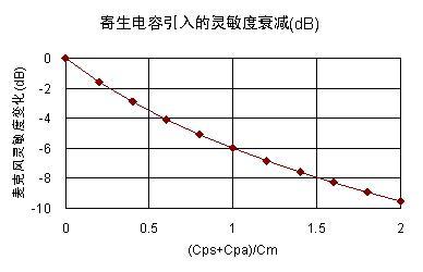
Figure 7 The effect of parasitic capacitance on microphone sensitivity
In a typical 4015 microphone, the input parasitic capacitance Cpa of the amplifier is about 3.5pF (TF202). At this time, Cpa has little effect on sensitivity; but when the microphone size is reduced to 3015, due to the reduction of Cm and Cps, Cpa It will additionally cause a 3 ~ 4dB sensitivity drop, so in the 3015 microphone, the actual voltage gain of the TF202 will be reduced from -2dB to about -6dB, resulting in deterioration of the microphone sensitivity and signal-to-noise ratio; when the microphone size is further reduced to 2.5mm At this time, Cpa will deteriorate the sensitivity of 6 ~ 8dB, making it completely unusable.
Even if a microphone amplifier with a smaller input capacitance Cpa is selected, such as the ACT503D electret microphone amplifier provided by Beijing Zhuo Rui Micro Technology Co., Ltd., its Cpa is about 0.1pF. It still needs careful consideration in the design of the microphone structure and substrate design. In order to make full use of the excellent characteristics of the amplifier. For example, in a 4011 microphone using copper ring contacts, assuming that Cm is 4pF and Cps is 2.2pF, when using TF252, Cpa is 3.1pF. When switching from TF252 to using ACT503D, although the signal attenuation introduced by the parasitic capacitance of the circuit is improved by 20 * log10 ((4 + 2.2 + 3.1) / (4 + 2.2 + 0.1)), about 3dB. However, if the copper ring contact is further changed to copper wire point contact and the substrate design is optimized to reduce Cps to 1pF, then the sensitivity can be increased by about 2dB. Since the DC gain of the ACT503D is 6dB, the final microphone sensitivity is better than the use TF252 should be nearly 10dB higher, so that it is easy to realize a high-sensitivity thin microphone product.
In a miniaturized microphone, due to the small volume of the back acoustic cavity and the small area of ​​the diaphragm, the acoustic sensitivity is low, and it is necessary to use a microphone amplifier with higher gain to obtain proper microphone sensitivity. In such a microphone, the effect of Miller capacitance will appear significantly, resulting in attenuation of the amplifier's gain. Because the Miller capacitance is related to the JFET Crss, the typical JFET Crss is about 0.7pF ~ 1.1pF, so in the miniaturized microphone, the use of high gain JFET is greatly limited. Similarly, RS908 / RS916 in small microphone applications, its actual magnification will decrease dramatically. The ACT503D provided by Zhuo Rui Micro Technology adopts ghost current output mode, and its equivalent Crss is less than 0.05pF, so it has a greater advantage in high-gain voltage amplification.
Actual microphone trial installation data
Figure 8 shows the sensitivity distribution of an ultra-thin 4mm microphone product using ACT503D provided by Beijing Zhuorui Micro Technology Co., Ltd. It can be seen from the figure that the yield rate in the range of 40 + -2dB reaches more than 88%. Table 1 shows typical signal-to-noise ratio test results.
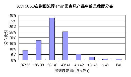
Sensitivity distribution of ACT503D in 4mm ultra-thin microphone

Table 1: SNR of ACT503D in 4mm ultra-thin microphone
Figure 9 shows the sensitivity distribution of a 3mm microphone product using ACT503D. It can be seen from the figure that the yield rate in the range of -42 + -2dB is over 80%. Table 2 gives typical signal-to-noise ratio test results.
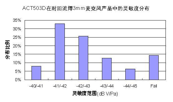
Figure 9 Sensitivity distribution of ACT503D in 3mm ultra-thin microphone

Table 2 Sensitivity and SNR of ACT503D in 3mm microphone
Low Voltage STA Cable is a type of Power Cable that is designed for use in low voltage applications. It is commonly used in industrial and commercial settings for the transmission of electricity between power sources and electrical equipment.
Steel Tape Armored cable is made up of a number of different components, including a conductor, insulation, and an outer sheath. The conductor is typically made from copper or aluminum and is responsible for carrying the electrical current. The insulation is used to protect the conductor and prevent the flow of electricity from escaping. The outer sheath is used to protect the cable from damage and to provide additional insulation.
The steel tape armor provides additional protection to the cable and helps to prevent damage from external factors such as moisture, chemicals, and physical impact. The armor is made up of a layer of steel tape that is wrapped around the cable, providing a strong and durable layer of protection.
Low Voltage STA Armored Cable is available in a range of different sizes and configurations to meet the specific needs of different applications. It is commonly used in underground installations, as well as in areas where there is a risk of physical damage to the cable.
Copper Low Voltage Cable,Armored Underground Electrical,XLPE STA Armoured Power Cable,STA Armored LV Underground Cable,LV Steel Tape Armoured Cable
Ruitian Cable CO.,LTD. , https://www.rtpowercable.com