The Hall sensor is a magnetic field sensor fabricated according to the Hall effect. The Hall effect is a kind of magnetoelectric effect. This phenomenon was discovered when Hall (AHHall, 1855-1938) studied the conductive mechanism of metal in 1879. Later, it was found that semiconductors, conductive fluids, etc. also have this effect, and the Hall effect of semiconductors is much stronger than that of metals. Various Hall elements made by this phenomenon are widely used in industrial automation technology, detection technology, information processing, etc. aspect. The Hall effect is the basic method for studying the properties of semiconductor materials. The Hall coefficient measured by the Hall effect experiment can determine important parameters such as conductivity type, carrier concentration, and carrier mobility of the semiconductor material.
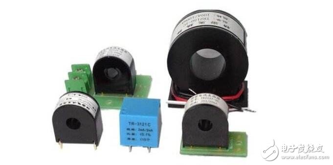
Hall sensor has been widely used in electrical measurement, automatic control and computing devices due to its advantages of no contact, small size and simple structure. Since Hall sensors generate many errors, although various compensation measures have been taken at present, it is difficult to effectively compensate various errors with only one compensation circuit. To this end, this paper designs a circuit that can effectively compensate for various errors without using a compensation circuit.
Main error and cause
1. Zero error
The zero error is caused by the unequal potential. The main reason for generating the unequal potential is that the two Hall electrodes are not mounted on the same equipotential surface; the uneven distribution of materials causes uneven distribution of resistance, poor contact of the control electrodes, and uneven current distribution.
2. Parasitic DC potential error
The main reason for generating parasitic DC potential is that the control electrode is in poor contact with the Hall element, forming a non-ohmic contact; the two Hall electrodes are asymmetrical in size, so that the heat capacity of the two electrodes is different, the heat dissipation state is different, and the temperature difference potential between the two electrodes occurs. , causing the Hall element to produce temperature drift.
3. Induced zero potential error
When the Hall element operates in an AC or pulsating magnetic field, even if the control current is not applied, the Hall terminal has a certain output due to the asymmetrical distribution of the Hall pole, and its magnitude is proportional to the pulsation frequency of the magnetic field, the magnitude of the magnetic induction intensity, and the two The sensing area formed by the electrode leads.
4. Self-excited magnetic field zero potential error
When the Hall element is connected to the control current, this current also generates a magnetic field, called the self-excitation magnetic field. When the electrode leads are asymmetrical, the magnetic induction strengths on both sides of the element are not equal, and the zero potential of the self-excited field will be output.
5. Temperature error

At present, in order to eliminate the above error, in addition to the attention in the process, the resistance compensation circuit is generally used for compensation, but the effect is still not satisfactory in the more precise measurement.
Method of eliminating various errors
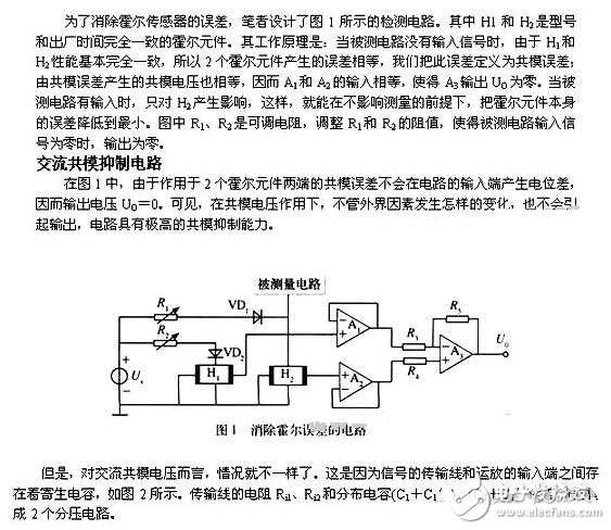
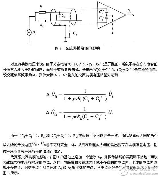
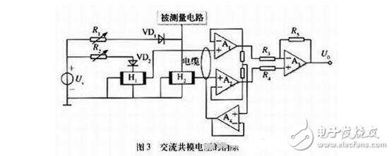
The potential drawn by the voltage follower composed of the operational amplifier A4 drives the shielding layer of the cable, so that the interference of the AC common mode voltage is well suppressed. The circuit shown in Figure 3 is suitable for various sensor circuits.
Hall sensor use precautions(1) In order to obtain better dynamic characteristics and sensitivity, it is necessary to pay attention to the coupling of the primary coil and the secondary coil. To be well coupled, it is better to use a single conductor and the conductor completely fills the aperture of the Hall sensor module.
(2) When a large DC current flows through the primary coil of the sensor, and the secondary circuit is not connected to the power supply or the secondary circuit is open, the magnetic circuit is magnetized, and residual magnetism is generated, which affects the measurement accuracy (so it is used Turn on the power and measurement terminal M) first. When this happens, demagnetize the first. The method is that the secondary circuit does not supply power, but an AC current of the same level is passed through the primary coil and the value is gradually reduced.
(3) In most cases, the Hall sensor has a strong resistance to external magnetic field interference. Generally, a magnetic field interference generated by a current twice the working current Ip between the modules 5-10 cm is negligible. However, when there is a stronger magnetic field interference, take appropriate measures to solve it. The usual methods are:
1 Adjust the module direction so that the external magnetic field has the least impact on the module
2 Shield the module with a magnetic shield against the magnetic field
3 Use modules with dual Hall elements or multiple Hall elements.
(4) The best accuracy of the measurement is obtained under the rated value. When the measured current is far below the rated value, to obtain the best precision, the primary side can use multiple turns, namely: IpNp=rated ampere-turns. In addition, the primary feeder temperature should not exceed 80 °C.
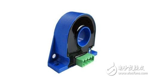
Hall sensor features (compared to common transformers)
1. The Hall sensor can measure the current and voltage of arbitrary waveforms, such as DC, AC, pulse waveform, etc., even for the measurement of transient peaks. The secondary current faithfully reflects the waveform of the primary current. Or ordinary transformers can not be compared with it, it is generally only suitable for measuring 50Hz sine wave.
2. The primary side circuit and the secondary side circuit are completely electrically insulated. The insulation voltage is generally 2KV to 12KV, and the special requirement is up to 20KV to 50KV.
3, high precision: accuracy in the working temperature zone is better than 1%, the accuracy is suitable for any waveform measurement. Ordinary transformers generally have a precision of 3% to 5% and are suitable for 50Hz sinusoidal waveforms.
4, good linearity: better than 0.1%
5, good dynamic performance: response time less than 1μs tracking speed di / dt higher than 50A / μs
6. The excellent dynamic performance of the Hall sensor module provides a critical basis for improving the performance of modern control systems. Compared with this, the common transformer response time is 10-12ms, which can no longer meet the needs of the development of the work control system.
7. Working frequency bandwidth: The accuracy is 1% in the frequency range of 0-100 kHz. The accuracy is 0.5% in the frequency range of 0-5 kHz.
8. Measurement range: Hall sensor module is a system product, current measurement up to 50KA, voltage measurement up to 6400V.
9. Strong overload capability: When the primary current is overloaded, the module is saturated and can be automatically protected. Even if the overload current is 20 times of the rated value, the module will not be damaged.
10. The module is small in size, light in weight and easy to install. It does not cause any loss in the system.
11. The “capacitance†between the primary and secondary of the module is very weak. In many applications, the various effects of the common-mode voltage are usually negligible. When the high-voltage variation of several thousand volts/μs is reached, the module has its own Shielding effect.
12. The high sensitivity of the module makes it possible to distinguish weak signals on the "high component", for example: to distinguish a few milliamps of AC component over a few hundred amps of DC component.
13, high reliability: failure rate: λ = 0.43 ╳ 10-6 / hour
14. Strong resistance to external magnetic field interference: The error caused by the magnetic field interference generated by a current twice the working current (2Ip) at 5-10cm from the module is less than 0.5%. For most applications, the external magnetic field is resistant. Interference is sufficient, but appropriate measures should be taken for interference with very strong magnetic fields.
12V 220V Inverter,12V To 220V Car Inverter,12V 220V Car Power Inverter,12 Volt Inverter Mini
GuangZhou HanFong New Energy Technology Co. , Ltd. , https://www.gzinverter.com