Design considerations for global short-range wireless systems in unlicensed bands below 1 GHz
The term short-range wireless devices covers wireless transceivers that enable one-way or two-way communication without causing interference to other wireless devices. SRD is widely used and can provide many different services. The more popular applications are: remote control applications in home or building automation systems, wireless sensor systems, alarms, cars (including remote keyless car door locks and remote car startup), and voice and Wireless transmission of video When selecting a wireless communication frequency, designers of wireless systems for short-range wireless devices must be very careful. In most cases, assuming that specific specifications and conditions of use can be met, the frequency range that can be selected is limited to unlicensed bands. Table 1 lists the available frequency bands for short-range wireless devices worldwide.
When designing a universal system, designers usually choose the 2.4GHz band. In fact, 2.4GHz has become Bluetooth, WLAN and
ZigBee and other standards are the preferred operating frequency bands. In the wireless phone or 802.11a version of WLAN applications, the 5.8GHz band also occupies some status.
However, for systems that require longer transmission distances and lower power consumption, the frequency bands below 1GHz are of great concern because of fewer coexistence issues and longer transmission distances, because both aspects of performance affect power consumption, and Power consumption is an important consideration in battery-powered applications.
The increase in the transmission distance of the low-frequency transmitter can be expressed by the simplified Friis transmission equation, which gives the relationship between the power Pr on the receiving antenna and the power Pt delivered to the transmitting antenna.
It is assumed here that both antennas have unity gain. This equation shows that for a fixed transmit power Pt, the received power will decrease with the square of the distance d and the square of the frequency f (or increase with the square of the wavelength λ). If the received power is lower than the minimum power required to correctly demodulate the signal (called sensitivity), the link will be interrupted.
Worldwide allocation of frequencies below 1 GHz Table 2 provides a more detailed description of communication frequency standards for short-range wireless devices below 1 GHz. Not all standards are listed here. For more details, please check the relevant links.
The 433MHz frequency band is one of the frequencies that can be used worldwide. In Japan, the frequency needs to be adjusted a little. Most transceivers with flexible frequency tuning can easily handle this problem, as shown in Figure 1 (ADF7020, or ADF7021). However, the available bandwidth of the 433MHz band is less than 2MHz, and it is usually not used for the transmission of voice, video, audio and continuous data, so it is often used in applications such as keyless door lock systems and basic remote control.
Table 3 shows the number of channels, effective radiated power (ERP) and duty cycle required for the extended frequency band (less than 870MHz) of the European standard when using FHSS technology. When meeting the listen-before-talk (LBT) or duty cycle limits, the bandwidth can be as high as 7MHz, while in the past only a bandwidth range of 2MHz was available.
Listen first and say that it is a "polite" communication protocol. It will scan the activity on the channel before starting transmission. It is also called clear channel assessment (CCA). limits.
In addition to FHSS, direct sequence spread spectrum (DSSS) is also adopted in the new European specification. In the DSSS system, the narrow-band signal is multiplied by a high-speed pseudo-random number (PRN) sequence to obtain a spread spectrum signal. Each PRN pulse is called a "chip", and the rate of the sequence is called a "chip rate". The extent to which the initial narrowband signal is spread is called the processing gain, and is equal to the ratio between the chip rate (Rc) and the narrowband data symbol rate. Figure 2 compares the spectrum of FHSS and DSSS.
2. Low power spectral density-minimum interference introduced in existing narrow-band systems;
3. Security—Because spread spectrum / de-spread spectrum is implemented, it has strong resistance to interference;
4. Alleviate multipath effects.
Wideband modulation methods other than DSSS or FHSS In addition to FHSS and DSSS wideband spread spectrum modulation methods, European specifications also support FSK / GFSK (Gaussian Frequency Shift Keying) modulation technology with a bandwidth greater than 200 kHz. Table 4 gives the main specifications applicable to European broadband modulation schemes (including DSSS).
The ADF7025 ISM band transceiver is a device that supports the FSK modulation broadband standard. In order to work in the 865 ~ 870MHz sub-band, the device design must meet the limits of maximum occupied bandwidth (99%) and maximum power density, and the limit of the maximum power of the channel (or frequency band) edge is -36dBm. If the ADF7025 is set according to the parameters in Table 4, the device can meet these three constraints. Figure 3 is the result of ADF7025's wideband modulation test, which occupies a bandwidth of 1.7569MHz and a peak spectral density of -1.41dBm / 100kHz.
2. For digital modulation systems, within any 3 kHz bandwidth during any continuous transmission interval, the power spectral density conducted from the transmitting end to the antenna is not greater than 8 dBm.
Anyone wishing to use a non-FHSS system must usually limit the radiated field strength to 50mV / m (-1.5dBm
ERP), but in the case of "digital modulation", as long as the maximum power spectral density limit can be met, the maximum output power is 1W. Therefore, when using the ADF7025, the width of its FSK frequency deviation is sufficient to ensure that the 6dB bandwidth is greater than 500kHz, so 1W ERP is allowed. In addition, due to the wide signal bandwidth, the system can also achieve higher data rates (up to 384kbps for the ADF7025).
ADF7025's co-channel suppression varies in the same channel from -2dB (worst) to + 24dB, depending on the bandwidth of the interference source. This is comparable to a commercial 802.15.4 DSSS transceiver with co-channel rejection of -4dB, which uses an artificial interference signal that is an IEEE 802.15.4 modulated signal.
With these methods, similar broadband modulation systems can be used in the US and Europe, simplifying product development for the global market. The ADF7025 transceiver architecture can work not only in the "digital modulation" mode defined by the US standard, but also in the "broadband modulation" mode defined by the European standard.
Transient power requirements Design engineers should be aware of a new technical specification requirement in the European regulations, namely the limitation of transient power. Transient power is defined as the power that falls into the adjacent spectrum when the transmitter is turned on and off during normal operation. The latest specification adds this restriction to prevent spectral scattering.
As the current delivered to the power amplifier increases or decreases, the load seen from the voltage controlled oscillator (VCO) terminal also changes, which causes the phase-locked loop (PLL) to lose lock in an instant, and When the loop tries to regain the locked state, it generates stray radiation or spectral scattering. In those systems that only transmit intermittently, spectral dispersion can cause a significant increase in power falling into adjacent channels.
Figure 4 shows the spectrum scattering problem. The green line represents the PA output spectrum when the PA of the ADF7020 transmitter is turned on and off every 100ms. Obviously, a large amount of power falls into the channels on both sides of the carrier. During the test, the spectrum analyzer maintains the maximum hold state. The red line represents the output of the PA output when it gradually rises and falls in 63 steps every 100 ms, so it can be seen that the power falling into the adjacent channel drops significantly. SpecificaTIon 8.5 in the EN 300 220 specification limits the power that falls into these adjacent channels.
ADI's ADIsimLINK protocol software can be used with any ADF702x transceiver. The agreement for this plan for the world's sub-1GHz frequency band incorporates new European specifications and is based on the star network shown in Figure 5 (up to 255 endpoints).
The core of the protocol is a non-slotted, non-persistent, anti-collision carrier sense multiple access / collision avoidance (CSMA / CA) scheme, whose endpoint (EP) can monitor the channel before transmission (LBT) To avoid collision.
The gapless feature in the protocol means that endpoints can send data as soon as they have data, so the "listen before talk" operation must be performed first. This method also ensures that no synchronization is required. If the endpoint detects that the channel is busy, it will wait a random length of time before performing the next LBT. The number of waits is limited, so the protocol also has a non-persistent nature. In FHSS mode, the protocol uses this CSMA / CA system on each frequency hopping channel, so it can meet the LBT requirements of the new European standard.
The physical layer (PHY) and media access layer (MAC) parameters of the ADIismLINK protocol are highly configurable, which allows full evaluation of devices and systems. ADI also provides source code to simplify the system development process. The agreement is provided as part of the ADF702x development kit (ADF70xxMB2). Figure 6 is the overall system architecture of ADIismLINK.

Follow WeChat

Download Audiophile APP

Follow the audiophile class
related suggestion
'+ data.data.username +'
'; dom + ='12mm LED Metal Push Button Switch
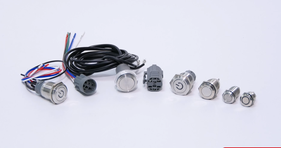
Yeswitch 12mm Metal Pushbutton switch is CUL & CE certified, it offering a rating of 2A/36VDC. Additional features include IP65 rating, with Momentary and Self-Locking operation function and a long operating life of up to 1,000,000 life cycles (Momentary) and 500,000 (Self-Locking)
The 12mm series LED Metal Switches require 12mm panel cut-out size. LED pattern options include Dot, E-ring and Power Logo and Many LED color options are available.
Specification:
|
RATING |
2A/36VDC |
|
SWITCH COMBINATION |
1NO |
|
OPERATION TYPE |
Momentary/Self-locking |
|
MECHANICAL LIFE |
Momentary 500,000 cycles Self-lock 500,000cycles |
|
ELECTRICAL LIFE |
50,000 make-and-break cycles at full load |
|
PANEL THICKNESS |
1-6mm |
|
INGRESS PROTECTION |
IP65, IK08/(Stainless) |

Our Advantages
From the purchase of raw materials to the finished product, all production process (product development/plating/mold and equipment processing/ metalpressing/ plasticinjection/semi-automatic and fully automated equipment assembly, etc.) are completed in the factory. Our metal pressing and plastic injection own the advantages of 100% self-made mold, from a single form to the various forms of application. And we continuously keep innovation and enhance the technology in order to collaborate with our customers to design the most sophisticated products. Yeswitch Electronics Co., Ltd., whether in production base or in quality assurance department in the head office, have professional equipment and technical personnel. In addition to the annual new product development, product improvement and testing are performed as annual plan to ensure that listed products maintain in best quality. Therefore, our long-term customers/partners, get the best quality of the switches.


LED metal pushbutton, Waterproof Metal Switch, UL metal switch
YESWITCH ELECTRONICS CO., LTD. , https://www.yeswitches.com