1. Why do you need to use the signal to rise (fall) when the length is shortened to determine whether it is a high-speed signal?
A: The more "sudden" the signal, the more frequency components need to keep the signal intact (wewean leaf transform knows; the general digital signal keeps 5 times the most, because taking 5 times the frequency has taken into account 90% of the energy of the signal). Signals of different frequencies have different transmission characteristics, and the wider the frequency band used for transmission, the more complicated the transmission characteristics. For example, the same 150M signal, if you take 7 times the frequency, the signal will look a lot better, but its transmission frequency will reach 1GHz; the characteristics of discrete components in the 150M-1G frequency band vary greatly, maybe which frequency will appear Wave phenomenon. Moreover, the signal is not "pure" 150M, the situation is much more complicated.
2. What are the differences between high-speed signals and ordinary low-frequency signals?
A: Considering the physical quantity, transmission system and circuit model considered.
Low frequency circuit system
The physical quantities are: current, voltage, resistance, capacitance, and inductance. The transmission system is a visible loop circuit. The circuit model is a discrete component circuit and a lumped model.
Microwave circuit system
The physical quantities are: power, loss, characteristic impedance, and transmission mode. The transmission system is in the form of visible invisible medium loops, atmosphere, waveguides, transmission lines, and the like. The circuit model is Maxwell's equation and equivalent distribution model.
3. How do you view the transmission process of high-speed signals, if not like the "electronic flow" in low-frequency systems?
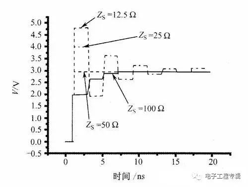
A: The transmission of electromagnetic waves is that electromagnetic waves are alternately established in the transmission medium to establish electric and magnetic fields. This alternating process will continue in a certain direction, although the strength of the electric field will continue to weaken. The TEM model is commonly used in our analysis, which is to limit the direction of electromagnetic wave propagation in the Z-axis direction. In other words, not in front of the Z axis, or backward. Then, if an "obstacle" is encountered, part of the electromagnetic wave continues to be transmitted, while another part is reflected back and transmitted in the reverse direction. We define the ratio of the reflected voltage to the forward voltage of the electromagnetic wave transmission as the reflection coefficient.
4. Is the match the source or the terminal?
A: Although there is a matching problem between the source and the terminal, the matching of the terminal is more important because it is the best position to eliminate the reflection. In fact, many engineers mention matching and will default to terminal matching. Of course, in many cases, the terminal does not allow matching or the terminal matching mechanism does not work well, so it is necessary to match at the source. For example, the output pin of the clock chip must be connected to a 22Ω or 33Ω resistor, which is a typical source-side match. Source matching and terminal matching are not contradictory, except that the matching position is different from the object that eliminates reflection.
5. How to understand the “impedance†impedance?
A: For all ideal components, the impedance is defined as the ratio of the voltage across the conductor (vector) to the current (vector) flowing through the conductor. This definition is valid both in the time domain and in the frequency domain. Starting from this definition, then, for an ideal resistor, the voltage and current are always the same frequency vector, ie, the ideal resistance does not affect the frequency of the signal. For the ideal inductance and capacitance, we derive that the impedance is ZL=jwL and ZC=-jwC respectively. That is, the impedance of the inductor and capacitor are both frequency dependent quantities. Note that here is the ideal component! For non-ideal components, an equivalent model needs to be established to study. It should be noted that each time the electromagnetic wave passes through a wire Δx, it must establish a corresponding electromagnetic field, which corresponds to a transient impedance. If the Δx equivalent circuit of each unit on the transmission line is the same and its physical characteristics are identical, that is, each instantaneous impedance is uniform. Then, the instantaneous impedance can be positioned as the characteristic impedance of the transmission line. The transmission line system is "continuous and uniform."
6. How should the transmission line structure be understood?
A: Can an independent point constitute an electric field? The answer is no. If you look at a point on the wire as a high potential point in the two potential points, you have to have a low potential point. That is to provide a return path for the signal. note! Not only the ground plane in the usual sense, any conductor that can establish an electric and magnetic field connection with the signal line can provide a return path to the signal line. For a section of microstrip line, and the path that constitutes the structure of the transmission line includes: the microstrip line itself, the return path, and the medium between the microstrip line and the return path. Therefore, the characteristic impedance of this transmission line is actually a comprehensive result of the equivalent of various factors in the entire transmission line structure.
7. Why is 50Ω?
A; the first reason is compatible with previous products and systems, just like "the rail width is determined by the horse's ass"; the second reason is that the output impedance of CMOS is generally in the tens of ohms, and IBM's investigation shows that the board level The design is also 40Ω~80Ω is optimal.

Outdoor Led Screen,Outdoor Waterproof Led Screen,Waterproof Led Screen,Outdoor Led Display Screen
APIO ELECTRONIC CO.,LTD , https://www.displayapio.com