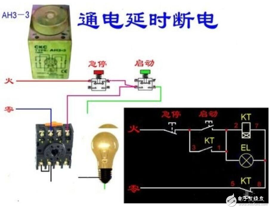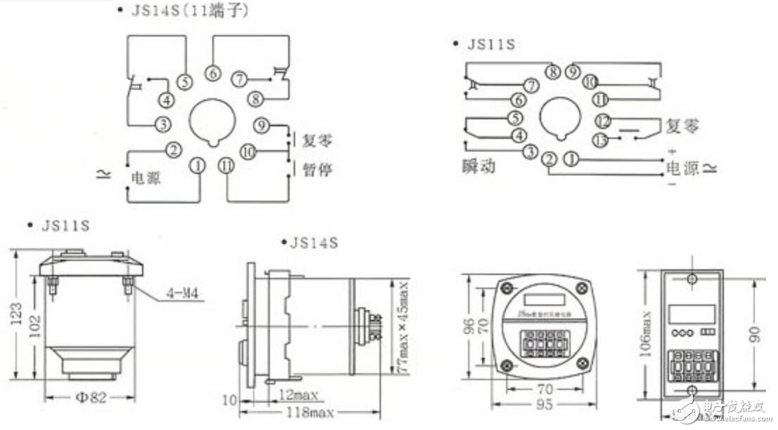
First, control wiring: You can think of it as a DC relay. 3, 7 are used to connect 12V control voltage; 2, 7 are used to connect 24V control voltage. Among them, 7 is regarded as the negative pole of direct current, and is connected to the neutral line when in use. 2 Connect the 220V live wire.
Second, work control: Although the control voltage is connected, whether it plays a control role or not is determined by the timer on the panel.
Third, functional understanding: It is a switch, single-pole double-throw, with a movable arm, just like the movable arm of a common knife switch. 8 is the active point and 5 is the normally closed point. When the relay does not move, the two are connected. When moving, 8, 6 are connected.
Fourth: Load wiring: the neutral wire or negative terminal of the power supply is connected to the neutral wire or negative terminal of the electrical appliance. Connect the live wire or positive pole of the power supply to pin 8, and connect the live wire or positive pole of the electrical appliance to pin 6, and pin 5 is not used when it is free.
Fifth, working principle: during the time when the timer is invalid, 8 and 5 are connected, which is equivalent to our usual light switch disconnected state. When it is effective, the relay acts, 8 and 6 are connected, and the electrical appliances are energized to work, which is equivalent to our usual light switch on state.
First preset the required delay time, and then turn on the power. At this time, the display will start timing from zero. When the preset time is reached, the delay contact will switch, and the digital display will keep the current number. Timing control.


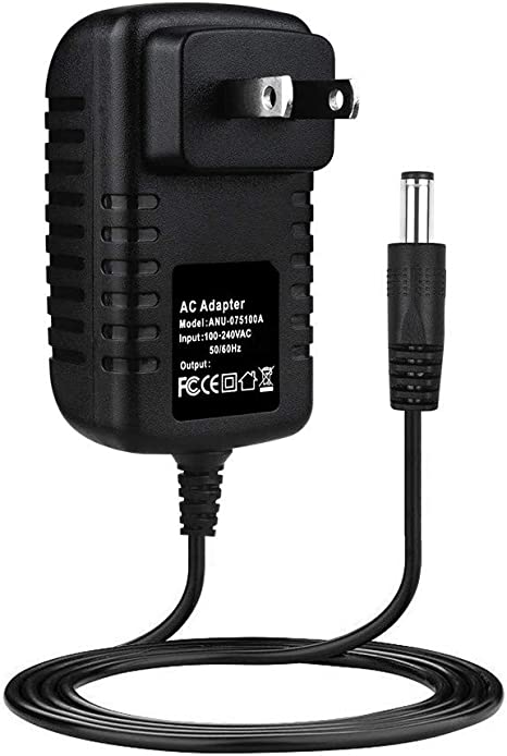
15v wall charger,15 Watt Power Supply,15v ac dc adapter,AC Wall Charger Power Adapter,AC/DC Charger Power Supply Switching Adapter,DC 15V Global AC / DC Adapter,15VDC Power Supply Cord Cable Wall Charger,15VDC800 Charger PSU
Shenzhen Waweis Technology Co., Ltd. , https://www.waweisasdapter.com