introduction
With the development of liquid crystal display technology, LCD liquid crystal display modules have become an important part of home appliances, display instruments and other electronic products. The liquid crystal display is used as a display terminal for various portable systems with its intuitive display and easy operation. LCD screens are characterized by low voltage, micro power consumption, no radiation, small size, etc., and are widely used in a variety of embedded products. ARM is a reduced instruction set computer (RISC) that is widely used in embedded system development due to its high performance, low cost, and low power consumption. ARM processors are almost in every field: industrial control, wireless communications, networking applications, consumer electronics, imaging and security products.
Therefore, this article describes a liquid crystal display design based on ARM and TFT6758.
1 Introduction to TFT6758 Controller
The TFT6758 LCD module is a dot-matrix LCD that displays graphics, Chinese characters, and various symbol information to provide a friendly human-machine interface. It is mainly for the staff, and displays the monitoring information so that the staff can clearly monitor the operation. The TFT6758 LCD module has a screen size of 2.2in and a dot pixel of 240&TImes; 320. It has a liquid crystal controller and a liquid crystal driver. It supports true color 262K color and the user interface is more gorgeous. The TFT6758 LCD module operates at 3.3V with a white LED backlight and can be connected directly to the controller using an 8-bit, 16-bit or 18-bit bus.
2 TFT6758 interface circuit
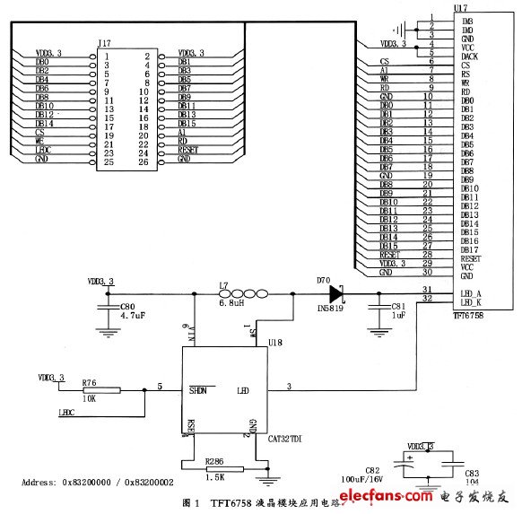
The TFT liquid crystal interface circuit is connected to the main board in the form of a PACK board, and its interface definition is as shown in FIG. Connect the RESET pin of the TFT6758 liquid crystal display module to the J1 connector and use the P0.22 of the LPC2292 to control the liquid crystal module reset. The CS6, WR, and RD pins of the TFT6758 LCD module are connected to the J1 connector and are connected to the chip select, write, and read signals of the LPC2292 on the motherboard. The RS pin uses the A1 connection. When A1 is high, it is data operation. When A1 is low, it is command (index) operation. That is, two different addresses are used to distinguish whether to send commands to TFT6758 LCD module or send data. . TFT6758 LCD module chip select signal: LCM_nCS0; 0x83200000~0x833FFFFF; Index/instruction operation address is: 0x8320000; Data operation address is: 0x83200002.

The backlight of the TFT6758 liquid crystal module is LED backlight. It is connected in series with four white LEDs. Therefore, to design the boost circuit, CAT32TDI is a boost chip specially used for white LED driving, which can drive 4 serial white LEDs. The CAT32TDI is the output shutdown control pin, which is controlled by the LEDC signal (connected to the PWM pin P0.21 of the LPC2292 of the motherboard, which can be used to control the brightness of the backlight), in order to ensure that the I/O connected to the LEDC is not configured as an output. It also illuminates the LED backlight, so a 10kΩ pull-up resistor R1 is connected. The CAT32TDI chip is a constant current output and the output is controlled by R2.
3 TFT6758 display principle
Each liquid crystal pixel on the TFT liquid crystal display is driven by a thin film transistor integrated therein. The TFT liquid crystal display has the characteristics of fast screen response, good contrast, high brightness, large viewing angle and rich colors.
In the text display mode, the management unit of the LCD display information is 8&TImes; 8 dot matrix, which is called a text display unit, and each text display unit corresponds to 8 consecutive storage units in the text display buffer. The character code is written to the text display buffer, and the dot matrix status information (8&TImes;8) is stored in RAM. Chinese characters are generally described by 16&TImes;16 dot matrix, which is divided into four 8×8 dot matrixes. Four character codes are used to describe a Chinese character, and four codes are written according to the positional relationship of the four parts. The text shows the buffer. The display of the LCD is closely related to the font data. The function of the display subroutine is to read the corresponding font data and send it to the LCD. The received font is displayed by the LCD at the corresponding position. However, the generation of font data is basically independent of the program, and the related content is only the content of the font data. Chinese characters sent to the LCD must be converted to a dot matrix array using the extracted font software for use in the program.
Pressure Lnstrument Controller
Pressure Lnstrument Controller,Instrument Weighing Controller,Instruments Digital Temperature Controller,Instrument Weighing Display Controller
Xiaogan Yueneng Electronic Technology Co., Ltd. , https://www.xyeloadcell.com