Summary
Since the advent of the Qi standard, wireless charging accessory products can take advantage of this industry-wide standard to wirelessly charge mobile devices without the need for a base station (wireless charging transmitter). One common method is to provide the consumer with a wireless charging protective case, back cover, battery pack or protective cover in which the receiver coil and electronic components are placed. This article will explain the system level requirements for this type of accessory, focusing on the interface between the accessory product and the primary mobile device. We will also discuss component selection in two ways, as well as a trade-off between the pin number interface between the accessory product and the main mobile device.
WPC (Qi) System Overview
Figure 1 shows the block diagram of a WPC inductive wireless charging system. The transmitter consists of an AC/DC power converter, driver, transmit coil, voltage and current sense and controller. The receiver consists of a receive coil, rectification, voltage regulation and controller. The system load can be any battery powered device, such as a mobile phone.
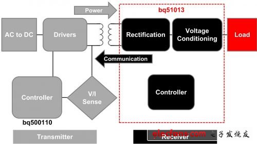
Figure 1WPC inductive wireless charging system structure
In the system, an AC current flows through the transmitter coil to form a coupled magnetic field through which electrical energy is transmitted from the transmitter to the receiver. If the receiver coil is very close (XY or Z size is less than 5mm gap), most of the transmitter field line will be coupled to the receiver coil. These coupled field lines form an AC current in the secondary winding that is rectified to produce a DC voltage that is used to power the phone or other portable device. Please note that the wireless charging link is actually a loosely coupled, coreless coil transformer.
WPC standard
A key to the rise of the wireless charging market is the standardization between different transmitters and receivers. Previously, companies selling wireless charging receivers had to provide a corresponding transmitter at the same time. This situation constrains the market acceptance of wireless charging and has led to the emergence of a large number of different types of wireless charging technologies that are incompatible with each other. The Wireless Charging Alliance (WPC) developed the first global standard to achieve versatility in 5W power level transmitters and receivers [1]. The Qi (pronounced "chee") standard defines the operating frequency, operating voltage, and basic coil configuration of a wireless charging system. In addition, a communication protocol is defined by which the receiver communicates with the transmitter, such as when the transmitter terminates the power supply (ie, enters a power-saving mode when the phone is no longer charging), how much power the receiver requires to provide, and whether the output power increases or Reduce and so on.
Accessory frame
One of the quickest ways to offer Qi standard products is to provide base station power (wireless transmitters) using industry-wide standards while providing accessory solutions with power or direct battery charging. In this case, the accessory solution refers to the wireless charging function, which is an option for mobile devices. The two most common accessory implementations are the protective case and the back cover. The protective case refers to a plastic case that contains a wireless charging circuit that can be securely clamped to the mobile device to provide power to the mobile device through some external contacts. The back cover is a replacement for the standard back cover of mobile devices, and a wireless charging circuit is also placed inside it. Another accessory solution is to place a wireless charging circuit in the battery pack of the mobile device to directly charge the battery.
Power accessories
Figure 2 depicts how a wireless charging receiver simulates the operation of a power adapter to provide 5V, 5W power to a mobile device. In this simplest implementation, there are only two contacts in total between the receiver and the mobile device: wireless charging and grounding. Since most of the first-generation Qi products still have a connection, Figure 2 also shows the process of charging via a wired adapter and wireless charging. Both power supplies are connected to a power multiplexer inside the mobile device. In general, the adapter power is selected by default and wireless charging is used when there is no adapter.
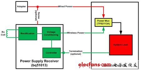
Figure 2 Wired input four-contact power supply accessory system architecture
Wireless charging should be interrupted during the wireless charging transmission when the connection adapter or battery is terminated. When the receiver detects a no-load condition, it sends a message to the transmitter to stop the power transmission, thereby achieving the above goal. This state can be simulated by turning on the wireless charging receiver switch of the multiplexer. With other communications, you can get more detailed information on the no-load state.
Double contact accessories
The two-contact solution is the lowest cost wireless charging output and receiver interface, but it still offers some limited functionality. With only two contacts, we can only connect the wireless power (ie 5V output) and ground to the mobile device, and the mobile device must detect when it switches between the adapter power and the wireless power. The main disadvantage of this solution is that it is difficult for the mobile device to inform the transmitter that charging has terminated. In a typical wireless charging system, the user starts charging when he goes to bed at night, and the charging generally lasts for about two hours. Once charging is complete, the receiver should send a message to the transmitter that terminates charging (as defined by the WPC protocol) so that the transmitter can enter a low power standby mode. However, the two-contact solution is terminated and can only be detected by the receiver by detecting if the output current has fallen below a certain threshold. Although this method allows the transmitter to enter standby mode, the supply current consists of the system current plus the charging current, which has many drawbacks.
Three-contact accessories
The three-contact solution has been improved over the two-contact solution. In addition to wireless power and ground, it adds a control signal. The controller signal can be an input to a wireless charging receiver and the wireless charging receiver is driven by a mobile device. A typical application is for a charger inside the mobile device to detect when charging is terminated and then notify the receiver of this status. The receiver in turn notifies the transmitter to terminate charging and the transmitter enters a low power standby mode. Since the mobile device is continuously powered by the battery, it will continue to assert the termination of charging to the wireless receiver for an indeterminate period of time, so that the total transmitter power consumption is very low throughout the charging cycle. In addition, the transmitter can utilize the termination charging information from the receiver to let the user know that the charging has terminated (eg, using an LED indicator). This method also allows for a more accurate determination of the end of charge state compared to a two-contact solution.
Four-contact accessories
Finally, the four-contact solution offers users more options than the solution above. With the four-contact solution, there are several different options to choose from. One is to provide two control signal inputs - one for sending a termination signal to the transmitter and the other for notifying the sender that the mobile device is using the default state. Figure 2 shows an alternative to a four-contact implementation. In this case, an external adapter can be used as an input to the device receiver, and the adapter FET gate drive signal can be an output from the receiver and connected to the mobile device. With this method, the receiver can detect the presence of the adapter, which turns off the wireless charging transmitter and then directly applies the adaptation voltage to the receiver. The adapter multiplexer architecture is detailed in the following sections.
Mobile device power multiplexer
The first wireless charging accessories that went on sale still left the cable adapter port next to the wireless charging input. It requires a power multiplexer between the two power supplies (wired and wireless). Figure 3 shows an example of a power multiplexer architecture. This method uses the receiver accessory to detect the adapter voltage (AD) and provides the gate drive (AD_EN) if an adapter voltage is present. The FETs must be wired in a back-to-back configuration to block reverse and forward conduction when the switch is turned off. Thereafter, once the adapter is present, the wireless charging receiver turns off the power transfer and keeps the gate drive active through the adapter power supply. This method requires at least one four-pin interface (wireless charging, AD, AD_EN, and GND) between the accessory and the mobile device.
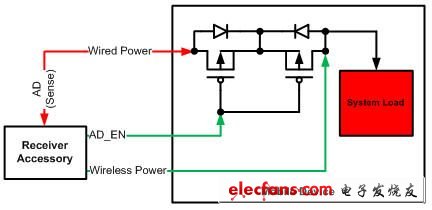
Figure 3. Power multiplex option for a single back-to-back FET
To reduce the number of pins required between the power supply accessory and the mobile device, we can use an automatic power multiplexer. Figure 4 shows this architecture, which no longer requires AD and AD_EN connections. Wired charging path, priority is obtained through VSNS connection. If a voltage is detected at VSNS, the wired charging path is activated. Otherwise, the wireless charging path is valid. In order for the receiver electronics to detect the presence of an adapter port to terminate the wireless charging transmission, it must monitor the power supply output current. By monitoring the output supply current, a true light load (eg, near zero output current) can be detected when the wireless charging path switch is turned off. The receiver then sends an instruction to the transmitter to terminate the power transfer.
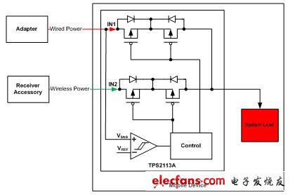
Figure 4 Power multiplex option using automatic switch
Battery pack accessories
Another way to provide wireless charging accessories is to integrate the electronic components and receiver coils into the mobile device battery pack. In this way, the end user can wirelessly charge the device, or the battery pack can be directly charged on the wireless charging sensor board (the use experience is similar to the charger). However, switching between wired chargers and wireless chargers is limited—it is not always possible to increase the number of pins between the battery pack and the system indefinitely.
Figure 5 depicts the architecture of the battery pack assembly and highlights the interface between the system and the battery pack. A temperature sensing sensor (NTC) embedded in the battery pack is used to ensure a safe operating temperature of the battery during charging. However, in this unique application, it can be used as a method for the receiver electronics to detect whether wire charging is effective or not. When the mobile system battery charger is active, the NTC resistor will have a certain voltage. When it is inactive, the NTC resistor is pulled down to the battery pack ground reference. Therefore, the receiver electronics in the battery pack can detect the presence of such a voltage and immediately turn off the wireless charger. This is only the case when the wired adapter is connected and the receiver is placed on the charging sensor board - not common, but providing twice the charging current is not conducive to battery safety.
After the receiver detects the NTC signal and takes corrective action, the wired charging path obtains the priority of use by the above method. However, using the detection algorithm of the mobile system, wireless charging can also be prioritized. Doing so will reverse the detection process. When the wireless charger is active, there is a voltage on the NTC pin and the mobile system will monitor this voltage on the NTC pin.
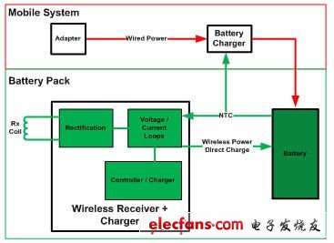
Figure 5 Wireless charging system architecture for battery pack accessories
Figure 5 depicts some of the voltage and current loop components that follow the rectification of the receiver electronics. It allows the controller to perform a charging algorithm that optimizes integration and efficiency by removing the voltage regulation stage in the power supply assembly.
references
1. Wireless charging alliance website: http://TIum.com/
2. For more details on WPC implementation and design challenges, please visit: http://www.TI.com/wirelesspower
About the Author
Tony Antonacci is a systems engineer in TI's bqTESLA receiver solution, working on system-level solutions and product definitions for wireless charging of portable devices. He graduated from the University of Tennessee, Knoxville, USA with a BS and MS in Electrical Engineering. Tony has filed a patent for Hall Effect IC integration.
Steve Terry is currently a design engineer responsible for the design of highly integrated linear switch mode battery chargers for portable applications and wireless charging solutions. In addition, he is the vice chairman of the Wireless Power Consortium Low Power Working Group. Steve has obtained three patents for analog IC design and power management IC design, and three other patents are under review. He graduated from the University of Tennessee in Knoxville with a Bachelor of Science, Master's and Ph.D.
Heating Pad For Feet,Heating Pad For Foot,Foot Heating Pad,Cordless Foot Warmer
Ningbo Sinco Industrial & Trading Co., Ltd. , https://www.newsinco.com