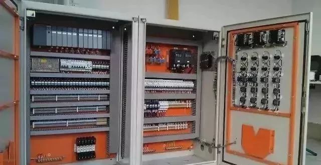
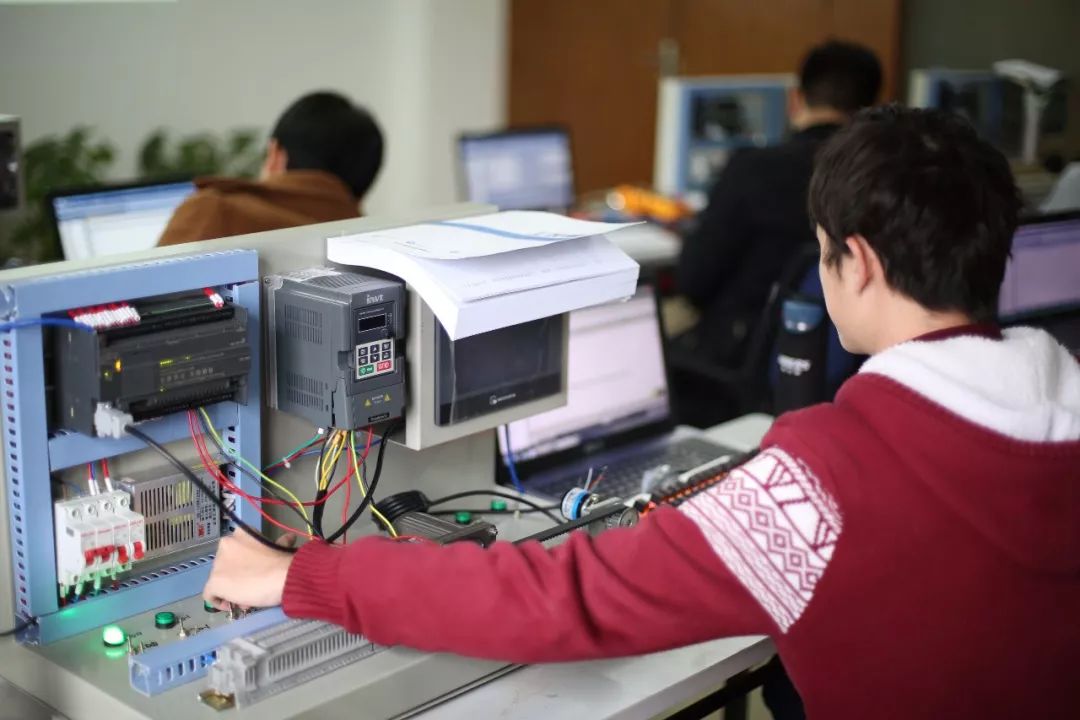
Commissioning work is a key task to check whether the PLC control system can meet the control requirements, and it is an objective and comprehensive evaluation of system performance. Before the system is put into use, it must undergo strict debugging of the system-wide functions until it meets the requirements and is signed and confirmed by the relevant user representatives, supervision and design. The commissioning personnel should be specially trained in the system and should be familiar with the composition of the control system and the use and operation of hardware and software.
Any problems found by the commissioning personnel during commissioning should be promptly contacted with the relevant design personnel. Modifications can be made only after the agreement of the design personnel. Changes must be made for detailed records. The modified software should be backed up. And do a good job of document editing and archiving. The debugging content mainly includes input and output functions, control logic functions, communication functions, and processor performance tests.

1, input and output circuit debugging
(1) Analog input (AI) loop debugging. To carefully check the address allocation of I0 module; check whether the loop power supply mode (inside power supply or external power supply) is consistent with the field instrument; use the signal generator to add signals to each channel on the field side, usually take 0, 50% or 100% Three points for inspection. For AI loops with alarms and interlocks, check the alarm interlock values ​​(such as high, low, and interlock points, and accuracy) to verify the correctness of the alarm and interlock status.
(2) Analog output (AO) loop debugging. According to the requirements of the loop control, the actuator (such as the valve opening, etc.) can be inspected manually with a manual output (that is, set directly in the control system). Usually, 0, 50 %, or 100 % of the three points are also checked; Closed-loop control checks whether the output meets the relevant requirements. For AO loops with alarms and interlocks, check the alarm interlock values ​​(such as the high alarm, low alarm, and interlock point and accuracy) to confirm the correctness of the alarm and interlock status.

(3) Switch input (DI) loop debugging. Short-circuit or disconnect at the corresponding field end, check the change of the LED corresponding to the channel address of the switch input module, and check the change of the channel's on and off at the same time.
(4) Switch output (DO) circuit debugging. Output points can be checked by the mandatory functions provided by the PLC system. By forcing, check the change of the light emitting diode corresponding to the channel address of the switch output module, and check the on and off changes of the channel at the same time.
2. Circuit debugging precautions
(1) For the digital input and output circuits, attention should be paid to maintaining the principle of consistency of state. Usually, the principle of positive logic is adopted, that is, when the input and output are live, the state is “ON†and the data value is “1â€; otherwise, it is the input and output. When the power is lost, it is in the "OFF" state and the data value is "0". In this way, it is easy to understand and maintain.
(2) For the heavy-duty digital input/output module, the relay should be isolated from the site. That is, the live contact should not be directly connected with the input/output module.
(3) When using the force function provided by the PLC, it should be noted that after the test is completed, the state should be restored; at the same time, it should not be forced to operate at excessive points to avoid damage to the module.
3, control logic function debugging
The debugging of control logic function shall be completed jointly with the design, process representatives and project management personnel. To apply the processor's test function to set the input conditions, check that the change in the output state is correct according to the processor logic to confirm the control logic function of the system. For all interlocking loops, simulate the interlocking process conditions, carefully check the correctness of the interlocking action, and make a good record of commissioning and confirmation.

The inspection work is the process of acceptance of the design control program software. It is the most complex, technically demanding and most difficult task in the commissioning process. Especially in the case of patented technology applications, special software, etc., it is necessary to carefully check the correctness of the control, and there should be a certain degree of operating margin, while ensuring the normal operation of the process operation and the system's safety, reliability and flexibility. .
4, processor performance testing
The performance test of the processor should be performed according to the requirements of the system specification to ensure that the system has the functions described in the specification and is stable and reliable, including system communication, backup battery and other special modules. Redundant tests must be performed on systems with redundant configurations. That is, a comprehensive review of the redundant design parts, including power redundancy, processor redundancy, I 0 redundancy, and communication redundancy.
(1) Power supply redundancy. When one of the power sources is cut off, the system should be able to continue normal operation and the system is free from disturbances; the power source that is powered off can return to normal after power is applied.
(2) Processor redundancy. Switch off the main processor power supply or switch the main processor's operation switch. The hot standby processor should be able to automatically become the main processor. The system is operating normally and the output is non-disturbed. After the power-down processor is powered up, it can return to normal and is in standby mode. .
(3) I0 redundancy. Select the input and output points that are mutually redundant and correspond to each other. The input module applies the same input signal and the output module indicates the connection status. Disconnect (or hot-plug, if allowed) redundant input and output modules, respectively, to check if their status can be maintained.
(4) Communication redundancy. You can check whether the system can communicate and run normally by cutting off the power of one of the communication modules or disconnecting a network. After the reset, the corresponding module status should automatically return to normal.
Redundancy testing, according to design requirements, should be performed on all redundantly designed modules. In addition, the system function check includes system self-check, file search, file compilation and download, maintenance information, backup and other functions. For more complex PLC systems, system function checks also include logic diagram configuration, loop configuration, and special I 0 functions.
SVLEC provide valve pulg form B 10mm with cable , the 24V valve plug always used as an Actuator . Form B valve plug with the pin space 10 cm , the free end cable can be field wireable with M12 or M8 connector . cable wire 3*0.75mm , we have 24V AC/DC with LED type , 24V AC/DC with LED and suppression , 110V AC/DC with LED and suppression , 0-230V AC/DC without electronics , 24V AC/DC with LED and suppression for select.
Valve plug,DIN43650 Valve plug,Form A Valve Plug,valve plug B form , Valve plug C form
Kunshan SVL Electric Co.,Ltd , https://www.svlelectric.com