It is generally believed that the number of input points is determined by the number of input signals of the system. However, in practical applications, the following measures can be used to save the number of PLC input points. The following FX1N series PLC is introduced.
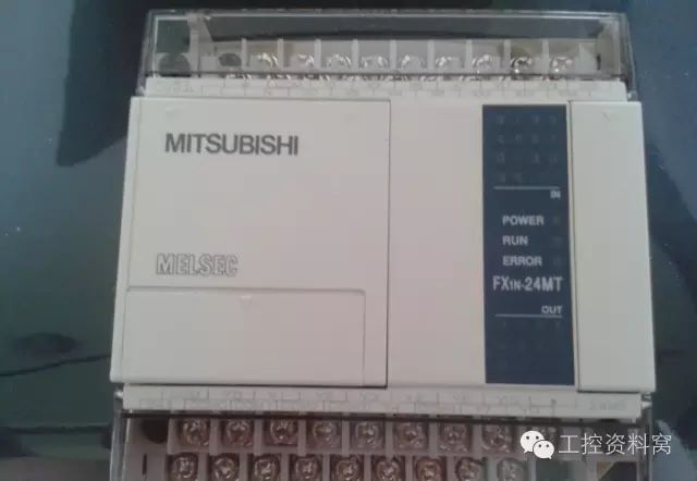
Method one: group input
As shown in the figure below, the system has two working modes: "manual" and "automatic". X000 is used to identify whether to use "automatic" or "manual" operation signal, the input signal when "manual" is SB0 ~ SB3, "automatic" when the input signal is S0 ~ S3, if according to the normal design ideas, then need X000 ~ X007 has a total of 8 input points. If the design is as shown in the figure below, only a total of 4 input points from X001 to X004 are required.
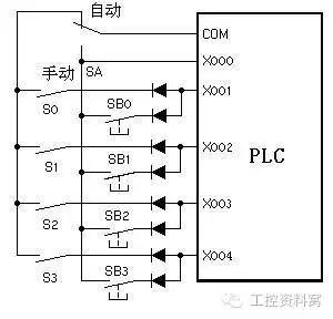
The diode in the figure is used to cut off the parasitic circuit. If there is no diode in the figure, the system is in automatic state. SB0, SB1, and S0 are closed and S1 is closed. At this time, the current flows out from the COM terminal and a parasitic circuit flows into the X000 terminal via SB0, SB1, and S0. This causes the input bit X002 to change to the wrong position. ON. After each switch is connected in series with a diode, the parasitic circuit is cut off and errors are avoided. However, using this method should consider the strength of the input signal.
Method two: matrix input
As shown in the following figure, a 4×4 matrix input circuit, which uses the PLC's four input points (X000 to X003) and four output points (Y000 to Y003) to implement the functions of 16 input points, especially for PLC output points And the input point is not enough. When Y000 is on, X000~X003 receive the input signal from Q1~Q4; when Y001 is on, X000~X003 receive the input signal from Q5~Q8; when Y002 is on, X000~ X003 accepts the input signal sent from Q9~Q12; when Y003 is turned on, X000~X003 receive the input signal from Q13~Q16. Connect Y000's normally open point with X000~X003 as input signal Q1~Q4; connect Y1's normally open point with X000~X003 as input signal Q5~Q8; connect Y002's normally open point with X000~X003 Input signals Q9 to Q12; the normally open point of Y003 is connected in series with X000 to X003 as input signals Q13 to Q16.
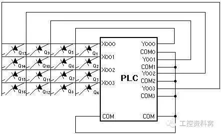
When using, pay attention to: In addition to wiring according to the above figure, there must also be corresponding software to cooperate to realize Y000~Y003 turns conduction; at the same time, ensure that the width of the input signal should be greater than Y000~Y003. , otherwise the input signal may be lost. The disadvantage of this method is that the sampling frequency of the input signal is reduced to one third, and the output points Y000-Y003 cannot be used anymore.
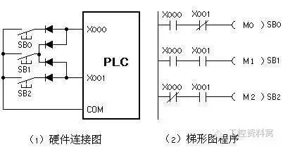
Method 3: Combining Inputs Input signals that do not turn on at the same time can be input in a combination code. As shown in the figure below, the three input signals SB0 to SB2 occupy only two input points, and M0 to M2 represent SB0 to SB2, respectively.
Method 4: Multiplication of input points In a traditional relay control system, a master command (button, switch, etc.) produces only one function signal. In the PLC control system, an input device can generate different signals under different conditions. For example, a button can be used to generate a start signal and a stop signal. As shown in the figure below, only one button is used to control the "on" and "off" of Y000 through X000. That is, when Y000 is turned on for the first time, Y000 is “ONâ€, and when Y000 is turned on again, Y000 is “OFFâ€. This method is called “non-self-locking buttonâ€.

Method 5: Combining input contacts Combine input inputs of certain digital input devices with the same functionality (normally closed contacts in series, normally open contacts in parallel). Some protection circuits and alarm circuits often use this method.
If some of the external input signals always appear in ladder diagrams as a combination of some “orphan†combinations, some of their corresponding contacts can be serially connected in parallel outside the programmable controller as a whole. Programmed controllers only occupy one input point of the programmable controller.
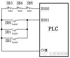
For example, a load can be started and stopped in multiple places. Multiple startup signals can be connected in parallel and multiple stop signals can be connected in series to the two input points of the programmable controller, as shown in the following figure. Compared to the method in which each start signal and stop signal occupy one input point, not only the input points are saved, but also the ladder diagram circuit is simplified.
Method 6: Some input signals do not enter the PLC
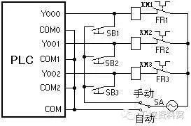
Some signal functions in the system are simple and involve a narrow range. The manual buttons and the thermal relay contacts of the overload protection in the diagram below are sometimes unnecessary as PLC inputs. Designing them in the hardware circuit of the PLC peripheral can also satisfy the control. Claim. If the external hardware circuit is too complicated, you should consider sending the relevant signal to the programmable controller.
Method 7: Use the RUN port
Most PLCs have a RUN port, and only when the port is connected (shorted with a wire from RUN to COM), the PLC can run. Therefore, some input signals can be sent to the RUN port. In the design of the elevator control system, the thermal relays normally used for overload protection of elevator traction motors, normally closed contacts for safety window switches, normally open contacts for safety gear switches, and normally closed contacts for upper and lower limit switches The contacts are serially connected to the connection between the RUN port and COM.
When the traction motor is overloaded, the safety window is opened, the safety gear is operated, and the top and bottom of the safety gear are faulty, the RUN port is cut off and the PLC stops operating. This not only ensures the safety of the elevator and the passengers, but also supervises the maintenance personnel for maintenance. This has the following two advantages. First, fault signals such as the traction motor overload and the safety window being opened are not sent to the PLC, and thus do not occupy the input of the PLC. Second, the software does not implement protection and can simplify the control procedure.
The etching process excels at producing tiny, lightweight components that are unaffected by hard-working tools or heat. It offers extreme precision, burr-free finishes, and a wide range of shapes and sizes that can meet the needs of any application.
We custom etching metal crafts with drawings provided by customers. The stainless-steel etching crafts widely use in drawing or Gift and various hardware decorations. The raw material we more use for metal crafts is SUS301 stainless steel and brass. We are equipped with professional metal etching equipment and exposure development equipment. Our customized metal etching crafts can achieve uniform etching line, burr-free finishes, no notch.
Etching Metal Crafts,Metal Crafts,Brass Etching Crafts,Stainless Steel Etching Crafts,Customized Metal Etching Crafts
SHAOXING HUALI ELECTRONICS CO., LTD. , https://www.cnsxhuali.com