The microphone adopts direct frequency modulation, the center frequency is 90MHz, the transmission power is about 0.5W, the maximum frequency deviation is 50kHz, and the transmission distance is not less than 50 meters.
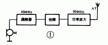
Circuit block diagram <br> The block diagram and schematic diagram are shown in Figures 1 and 2. The audio signal generated by the electret microphone acts on the transmitting junction of the modulator T1 as the modulation voltage. The magnitude of this voltage directly changes the junction capacitance of the emitter junction of the transistor. As a part of the loop parameters, the junction capacitance is about 45MHz, and the output frequency is increased to about 90MHz through frequency multiplication. After the FM signal is amplified by the high-frequency power amplifier, Launched by the antenna. 
Circuit principle 
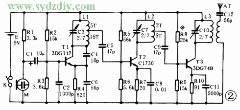
The modulation signal is coupled from the microphone M (CRZ-22) to the base of the modulator via C1, and R1 is the load resistance of the microphone M. The modulator consists of T1, R2, R3, C2, C3, C4, C6 and L1 to form a common base capacitor three-point oscillation circuit. In this circuit, the base is connected to C2, the base is grounded for high frequencies, and the collector is grounded for audio (the collector is connected to the power supply via L1). The collector junction capacitor Cc is actually connected in parallel across the oscillation circuit. As the audio signal changes, the oscillation frequency also changes accordingly, thereby obtaining a frequency-modulated signal.
Circuit characteristics 1. The modulator adopts direct frequency modulation method, and its frequency is stable and reliable.
2. Use electret condenser microphone. The microphone has a field-effect tube built-in radio follower, which has high sensitivity and wide frequency response. With this microphone, an appropriate amplitude modulation voltage can be obtained without adding an audio amplifier.
3. Adjustment components are available at all levels for easy debugging. T1 can adjust C3 to change the frequency, T2 can adjust C7 to get the frequency multiplier frequency, T3 can adjust C10 to get the maximum output.
Production and debugging 
The circuit board diagram is shown in Figure 3, and the size of the board can be scaled as required. Transistors, resistors, capacitors, and microphones can be selected according to the data given in Figure 2; the batteries can be 9V laminated batteries; L1, L2, L3 can be wound with Φ0.33 enameled wire, and the antenna can be used with a 20cm long leather flexible wire; K button Sub switch.
Follow the steps below when debugging 1. Check the soldered circuit board to ensure that the connection is correct. First measure whether the static resistance between the positive and negative power supply is short circuit or open circuit.
2. Measure the total current. The total current measured after power-on is about 50mA. With tweezers, short-circuit the b, e poles of T1 or C3, the current should have a significant change, and then short-circuit the b, e poles of T2 and T3.
3. Test carrier frequency. Use an ultra-high frequency millivoltmeter to measure that there should be a few volts of high-frequency voltage between the b pole of T2 and the ground. Observe with a digital frequency meter. C3 can be adjusted to a carrier frequency of about 45MHz. Test the base of T3 in the same way, and adjust C7 to get a carrier frequency of 90MHz. Then connect the frequency meter and UHF voltmeter between the antenna and the ground, adjust C10 so that the frequency is 90MHz, and the voltage can reach the maximum value. In this way, the carrier frequency is adjusted.
4. Modulation voltage measurement. First short circuit C3, use a millivolt meter to connect across R4, shout at the microphone, there should be an AC voltage indication, indicating that the microphone and T1 are working properly.
If you don't have an instrument, you can follow the above steps to try to receive and adjust C3, C7, C10 repeatedly until the receiving distance is far away, and the sound distortion is minimum.

Follow WeChat

Download Audiophile APP

Follow the audiophile class
related suggestion