As you can see from my previous blog, my inspiration and knowledge I have learned mostly from my father's influence on me. One suggestion has been haunting my mind: "Two measurements, one cut." However, as engineers, whenever we encounter a challenge in designing a control or power circuit for stepper motors, LEDs, and other peripherals, we expect to The system adapts to specific rules and conditions. We basically do two measurements, but only for a specific set of conditions. Any change after the event only means extra cost and evaluation time, which may be a pain point for any project. Or as my father said: "You have cut it, it is impossible to restore it to its original appearance!
So what happens when you need multiple systems or configured solutions? How do you ensure that you have a balance between having a system that can power the motor and adding other high-voltage devices after the design is complete? I recommend using a module or subset of the system to launch a design that can be scaled later.
Interface flexibility
The first thing you have to do is make sure you have the freedom to connect to your power drive. While it is a good idea to choose a host controller with enough general-purpose input/output (GPIO) to drive the output, it is becoming more and more difficult to implement a control scheme or program because each GPIO pin has its own call and execute operations. . The serial interface is convenient for this problem. Most processors have a series of internal interfaces as shown in Figure 1. These interface modules control memory or external sensors and even communicate with other processors.
Figure 1: Internal Block Diagram of MSP430TM
But for our system, the choice is simple. As I mentioned in the introduction, we are making this system drive multiple peripherals including stepper motors. For stepper motors, we need to ensure that the sequential output and the synchronous output are provided from the host.

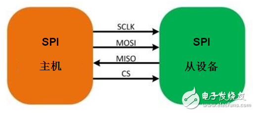
Figure 2: SPI master-slave connection
Interfaces such as the Serial Peripheral Interface (SPI) and I2C allow you to take advantage of the clock signal from the host or master (as shown in Figure 2), which can be extended by sharing serial data and clock lines. However, for design considerations, you want to maintain low cost because solutions with a large number of motors and LEDs require multiple iterations.
Some motors, LEDs, and other devices may not benefit from the internal serial interface that acts as a processor. In these cases, the SN74HC595 serial to parallel converter as shown in Figure 3 can be used. This device helps to transfer data sequentially to the output. I chose this part for design because it is easy to use, low cost, and allows designers to stack or daisy chain similar devices. Any other serial-to-parallel device such as the SN74HC164 or TCA9539 can also help with the task.
Figure 3: SN74HC595
Driving high voltage and high current
Unfortunately, you can't simply drive a high power load from a host microcontroller. But you can apply FETs to reduce the total current demand of the processor. This is actually one of the more popular threads in the design forum, and the main reason why the "Connect 3-V MSP430 to 5-V Circuit" application note is very popular. If you look at this application note, you will learn that ULN2003A is a simple solution.
Figure 4 showcases how the MSP430 microcontroller and ULN2003A can drive a 12V logic rail along with some motors and LEDs. This works out great because the ULN2003A can handle voltages up to 50V and currents up to 500mA/channel, which gives you ample range for motors And LEDs.
Figure 4 shows how the MSP430 microcontroller and ULN2003A drive 12V logic rails and some motors and LEDs. The result is very good, because the ULN2003A can handle voltages up to 50V and currents up to 500mA / channel, which provides a sufficient range for your motor and LED.
Figure 4: Connecting the MSP30 to high voltage and high current loads
Summary
Now that the conditions are ripe, you can connect the MSP430 MCU, SN74HC595, ULN2003A and CSD17571Q2 to create a flexible power supply structure that can be expanded in multiples of 8 channels, as shown in Figure 5.
Figure 5: Our Dynamic Drive System
ES Control Box is made of cold rolled steel plate, and its materials include carbon steel spraying plasÂtic and stainless steel series. There are several kinds of door-opening structure: single-door, double-door, visÂible window door and inside and outside double-door, etc. The box body is ten-bending body processed by proÂfessional equipment, which has strong firmness. Furthermore, ES also has the ability of resisting torsion and dispersing lifting force instantly. The module hole inside the box can be installed freely and quickly through the beam and vertical beam. PS and ES installation attachments are universal and have achieved design liberalÂization.
Being a quality driven firm, we do hard work to serve our customers in a well-systematized & successful way by presenting the optimum grade services. Our offered services are rendered by a crew of creative and talented personnel. We provide these services in accordance with the prevailing industry guidelines and set principles by using contemporary technology. In addition to this, offered services are highly in demand in the market for their outstanding features such as cost effectiveness, hassle free management and timely execution.
Carbon Steel Enclosure, ES Carbon Steel Enclosure, Metal Carbon Steel Enclosure, Metal Control Box, Detachable Control Box
Nantong Double Star Automation Equipment Co., Ltd. , https://www.nt-doublestar.com