The CAN-bus bus is one of the most widely used fieldbuses, and many highly skilled CAN engineers cannot answer very accurately when faced with the problem of how many CAN messages there are. Today we will clarify how many bits of a CAN message are from the most basic frame format.
What are the CAN message frames? CAN-bus communication frames are divided into data frames, remote frames, error frames, overload frames, and frame intervals. Data frames and remote frames have two types of standard frames and extended frames. Its frame type and its use are shown in Table 1:
Table 1 Frame Types and Uses

The data frame is divided into 7 segments from the structure, which are the start segment, the arbitration segment, the control segment, the data segment, the CRC check segment, the ACK response segment, and the frame end segment. Figure 1:
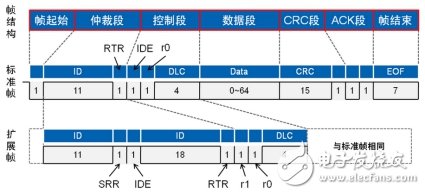
Figure 1 Standard data frame and extended data frame structure
· Frame start segment: This segment consists of a single dominant bit. It is allowed to transmit when the bus is idle. All nodes must be synchronized to the start bit of the data frame that starts transmitting.
· Standard frame arbitration segment: The arbitration segment of the standard frame is composed of an 11-bit ID code and a dominant bit RTR code, and the RTR code is a remote frame identifier bit;
· Extended frame arbitration segment: The arbitration segment of the extended frame consists of a 29-bit ID code, a dominant SRR code, a recessive IDE code, and a dominant RTR code.
· Standard frame control segment: The control segment of the standard frame consists of a unit explicit IDE, a reserved bit r0 and a 4-bit data length code DLC, and the DLC data segment is BCD-coded;
· Extended frame control segment: The control segment of the extended frame consists of two reserved bits r1 and r0 and 4 bits of DLC data segments. Both r1 and r0 are dominant padding. No matter whether the reserved bits are dominant or recessive at the time of reception influences;
· Data segment: A data segment is 8 bytes;
· CRC check segment: The CRC check segment consists of a 15-bit check code and a recessive bit-filled CRC delimiter. The CRC check range is the frame start, arbitration segment, control segment, and data segment.
· ACK segment: The ACK segment consists of an ACK code and a recessive bit ACK delimiter. The transmitting node sends two recessive bits in the ACK segment. When the receiving node has no error in the frame format before the received message ACK, he will A message is sent with an ACK code that is dominant.
· End of frame: consists of 7 consecutive recessive bits.
Ø Remote frame
The remote frame frame format is similar to the data frame, and is also divided into a standard frame and an extended frame, but the remote frame belongs to the message sent by the requesting sending node, and the data frame is the message of the sending node. As shown in Figure 2, the remote frame has no data frames.
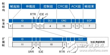
Figure 2 Structure diagram of standard remote frame and extended remote frame
Refer to the data frame to understand the structure of the remote frame, but there are differences between the two:
· SRR segment and RTR segment: the data frame is a dominant level and the remote frame is a recessive level;
· Node nature: The data frame is the format of the message sent by the sending node, and the remote frame is the format of the message sent by the node that is requested to send;
· CRC check range: The data frame is the frame start, arbitration segment, control segment and data segment, while the remote frame is the frame start, arbitration segment and control segment.
After understanding the standard message format of data frames and remote frames, some people may ask, why do the messages I sometimes see are different from the number of bits in your standard format?
Ø bit paddingCAN-bus is an asynchronous serial communication. This communication method does not have a clock line, so the clocks of the transceivers cannot be completely identical, and the clock inconsistency will cause a deviation. So in order to solve this problem, the CAN bus uses a synchronous method to calibrate the clock. The edge of the CAN-bus specified signal is the sync signal. As long as the signal changes, the node clock is synchronized. CAN-bus also specifies that the maximum period of synchronization is 5 bits.
But the question is, if there are 5 consecutive bits or even longer without edge transitions (for example, the data segment is all 0x56), how to solve it? CAN-bus regulates this situation. If the transmitted bit signals are the same for 5 consecutive bits, insert a bit with the opposite level. This is the CAN-bus "bit stuffing" rule. As shown in Figure 4.
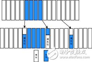
Figure 4 Bit Filling Rules
Ø 0x00 and 0x55Due to the existence of the bit filling rule, even if both frames are standard data frames, the message time will be different when sending different IDs or data segments. Figure 5 shows that the ID and data are 0x00 at 1M baud rate. Standard data frame message. The true message time of the original 108-bit standard data frame is 123us.
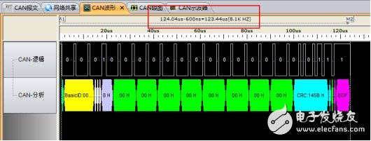
Figure 5 Standard data frame 0x00 message
The standard data frame message format of 0x55 is as shown in Fig. 6: the ID is 555H, the data segment is 55H, and the message does not have consecutive identical bits, so the padding bit is the least, and the 8-bit data segment bit time is the standard 8us. The text time is 108us.
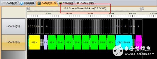
Figure 6 Standard data frame 0x55 message
The following table shows the difference in bit time between the four types of standard data frames, extended data frames, standard remote frames, and extended remote frames when sending different IDs and data.
Table 2 Different ID and data bits are filled in different numbers
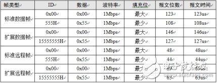
Through the message receiving and oscilloscope of CAN-Scope bus analyzer, each frame message can be matched with the waveform one by one, and the message time and waveform condition on the bus can be quickly analyzed to realize fast fault location and interference elimination of CAN bus. .
Pmic Led Drivers,Ic Pmic - Led Driver,Pmic Led Driver Ic Chip,Pmic Led Drivers Ic
Shenzhen Kaixuanye Technology Co., Ltd. , https://www.icoilne.com