Solar water heaters are very common in northern homes, but ordinary home solar water heaters have some disadvantages while conserving energy. Because the general solar water heater is basically placed on the roof of the building, the distance from the top of the building to the outlet tap is long, and a large amount of water is stored in the pipeline. The winter air in the north is relatively cold, and the water temperature in the pipeline is generally low. When people use hot water, it is usually necessary to drain the water in the pipeline. The farther the outlet is from the top of the building, the more cold water needs to be drained. This part of the water is usually wasted in ordinary households.
In response to this problem, we have designed a solar water-saving and water-storage control system in winter, which has the characteristics of manual adjustment, automatic sound and light alarm at appropriate temperature, and full utilization of water. Safe and reliable, low cost and significant water saving effect. It is very suitable for ordinary household solar water heaters. The transformation cost is very low and has a high promotion value.
1 system overall composition
The system mainly consists of a single-chip control module, a temperature measuring module, a solenoid valve control module, a button module, a water storage tank, a pump and the like. When people need hot water, press the start button, the MCU monitors the temperature of the water in the pipeline. When the water temperature does not exceed the set temperature, the cold water solenoid valve is opened, and the cold water flows through the solenoid valve to a water tank for storage. When the temperature exceeds the set temperature, the cold water solenoid valve is closed, and an audible and visual alarm is issued at the same time to remind people that it is now possible to wash with hot water. The cold water stored in the water tank can be sent back to the solar water heater by means of a water pump, and can also be used for flushing toilets and the like. The block diagram of the system is shown in Figure 1.

2 system main circuit components
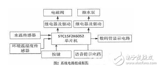
The system uses STC15F2K60S2 chip as the control core, which consists of temperature and humidity sensor SHT10, solenoid valve, water temperature sensor DS18B20, voice prompt circuit, digital tube display circuit and button circuit. The block diagram of the system circuit is shown in Figure 2.
2.1 main controller
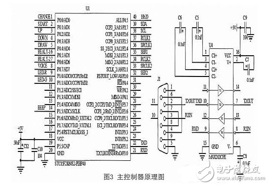
The STC15F2K60S2 microcontroller is used as the main control chip. This is a low-power, high-performance CMOS 8-bit microcontroller with an on-chip large-capacity 2048-byte SRAM. It integrates a high-resettable circuit and completely eliminates expensive external resets. The circuit has 8K in the system programmable FLASH memory, and 32 external bidirectional I/O ports that can be set in four modes, which are fast, inexpensive, and cost-effective. The schematic diagram of the main controller circuit is shown in Figure 3.
2.2 Water temperature detection circuit
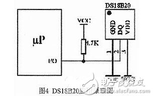
The water temperature test uses the commonly used DS18B20 digital temperature sensor with a waterproof stainless steel jacket on the outside. The DS18B20 is a single-bus sensor whose output is digital. It can directly read the digital quantity representing the temperature into the MCU for processing without using an additional AD converter. Its package form is TO-92, which is relatively small. To facilitate the measurement of water temperature, the DS18B20 is placed in a waterproof stainless steel sleeve and sealed with glue to allow us to measure the water temperature. The DS1B 20 can be set to a 12-bit conversion accuracy with a resolution of 0.0625 ° C and a measurement accuracy of ± 0.5 ° C to meet the needs of household water temperature measurement. The application schematic of DS18B20 is shown in Figure 4.
2.3 digital tube display circuit
The digital tube display adopts a 0.5-inch common anode digital tube, which is intuitive and convenient for the elderly in the family to view. The digital tube driver uses a serial-in and out-out 74HC595 chip driver for dynamic scanning, saving valuable I/O resources. The 74LS595 has a large driving capability and can directly drive the display of the digital tube. The schematic diagram of the digital tube display circuit is shown in Figure 5.

2.4 Solenoid valve and pump control circuit
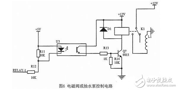
When the single-chip solenoid valve (or pump) control pin outputs a low level, the triode is turned on, the relay acts, and the solenoid valve (or pump) is turned on; otherwise, the triode is turned off, the relay does not operate, and the solenoid valve (or pump) is turned off. . The schematic diagram of the solenoid valve (or pump) control circuit is shown in Figure 6.
2.5 voice prompt circuit
The system uses the voice chip ISD1820 to implement the voice prompt function. US ISD has introduced a single-chip 8-20s single-segment voice recording and playback circuit ISD1820, which uses CMOS technology and includes oscillator, mic preamplifier, automatic gain control, anti-aliasing filter, speaker driver and FLASH array. It can perform voice recording and playback of about 10s, high quality and natural voice reproduction, few external components, simple circuit connection, convenient control, low cost, and can be controlled by single chip microcomputer. When the system detects that the water temperature in the pipeline exceeds the set temperature, the voice prompt circuit emits a sound reminder under the control of the single chip microcomputer. The schematic diagram of the voice prompt circuit is shown in Figure 7.

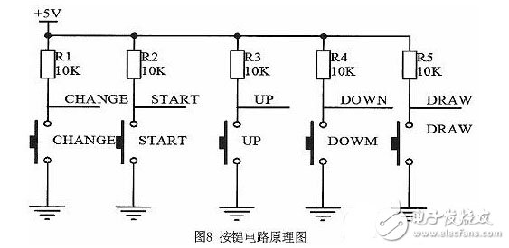
2.6 button circuit
The buttons use independent buttons, mainly water temperature / ambient temperature switch button, start / stop button, temperature rise button, temperature drop button, pump pump button. The button function is direct, with the digital tube display, the operation is convenient and intuitive. It is very convenient for the elderly in the family. The key circuit schematic is shown in Figure 8.
3 control system software design
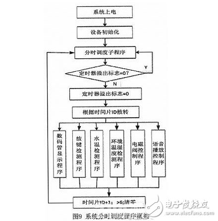
In the software design, the advantages of the IAP15F2K60S2 single-chip microcomputer are fully utilized. According to the characteristics of the DS18B20 and SHT10 sensors, as well as the requirements of button scanning and digital tube dynamic display, the time trigger mechanism is used for software design. The system tick clock is generated by the STC's MCU timer counter 0, and then different time slices are generated. The system performs different tasks in different time slices. The system time-sharing scheduler framework is shown in Figure 9.
4 Conclusion
Based on the investigation of the application requirements of household solar water heater users and the current problem of wasted water, a water-saving control system based on single-chip control was designed. The system can realize the functions of cold water flow control, real-time display of pipeline temperature, environmental temperature and humidity detection, voice prompts, etc., and has a good human-machine interface. Through the trial operation of the system in the home, it shows that it solves the problem of water waste in the winter of household solar water heaters. It is economical and practical, enough to meet the water-saving needs of users, and provides great convenience for people's daily life.
Push Button Membrane Swtich,Silicone Rubber Membrane Switch,Standard Membrane Switch,Single Key Membrane Switch
CIXI MEMBRANE SWITCH FACTORY , https://www.cnjunma.com