With the increasingly serious urban environmental pollution problem, the control of automobile exhaust is getting more and more attention, and many countries have carried out research on electric vehicles. However, electric vehicles have weaknesses such as short driving range and poor power performance, and the cost is too high. At present, they cannot be put into the market in large quantities. In order to take into account the advantages of traditional fuel vehicles and electric vehicles, research on hybrid vehicles has begun at home and abroad.
Since hybrid vehicles have two sets of drive systems, information exchange and coordination between the drive system and the vehicle control unit (VCU) is particularly important. The CAN (Controller Area Network) bus is the controller area network, which is a serial communication network that effectively supports distributed control or real-time control. It belongs to the field bus category. The structure is simple, the operability is good, and the price is low, so it is widely used in industrial control.
TMS320X24X is a series of chips designed by TI for digital motor control. Compared with the TMS320C240 or TMS320F240 of the same series, the TMS320F241 has the CAN module embedded in addition to the latter's basic functions, so it is very suitable for the control of hybrid vehicle motor drive systems.
1 Main features of TMS320F241
Compared with TMS320X240, TMS320F241 has the following differences in addition to an extra CAN module:
• TMS320X240 has dual 10-bit A / D converters, 16 input channels, and the conversion time is 6 μs; while TMS320F241 has only one 10-bit A / D converter, 8 input channels, and the conversion time is 1 μs.
• There are 3 timers / counters, 4 capture units and 9 PWM outputs (6 Full PWM and 3 Simple PWM) in the event manager of TMS320X240; and only 2 timers / counters, 3 in the event manager of TMS320F241 A capture unit and 6 PWM outputs (6 Full PWM), the counting method of the counter also has two modes of single rising edge and single rising / falling edge.
TMS320F241 has 8K on-chip Flash, no extended RAM interface, debugging is not very convenient. But you can use the same series of TMS320F243EVM board for debugging, and the program can be transplanted to the TMS320F241 chip for almost different modifications.
2 Brushless DC motor control system solution
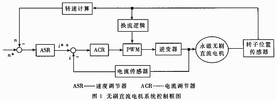
Figure 1 is a block diagram of the motor system control, using conversion and current double closed-loop control.

The rotor position is detected by the Hall element, which is three overlapping signals with a phase difference of 120 degrees (electrical angle) and a pulse width of 180 degrees (electrical angle). The rotation speed can be obtained from the rotor position, and then the calculated value of the current; and the actual current can be detected by the current sensor, the duty cycle of the PWM signal is adjusted according to the difference between the current given value and the actual value, and the current signal The rotor position triggers the corresponding power switching device, so as to achieve the purpose of controlling the motor speed.
The inverter uses an IPM intelligent power module, which contains power switching devices and drive circuits, as well as detection circuits for process voltage and overcurrent. The switching devices are IGBTs.
Each functional module (including ASR, ACR, PWM, commutation logic and speed calculation) in the motor control strategy is implemented by the TMS320F241 chip.
3 TMS320F241 peripheral design
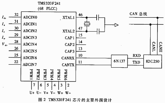
Figure 2 is the main peripheral wiring diagram of the TMS320F241 chip. The instructions are as follows:  Connect a 5MHz crystal between XTAL1 and XTAL2 to provide the system clock.
The pins CAP1, CAP2, and CAP3 of the three capture units are connected to the output of the Hall element. The rotor position signal is stored in the buffer of the capture unit, and the rotor speed can be obtained after calculation.
In the 8-bit input channel of the A / D converter, 5 channels are used, and the input quantities are DC bus current Idc, voltage Vdc, and motor three-phase currents Iu, Iv, and Iw; the other three channels are grounded through resistance.
The 6 PWM outputs are connected to the control terminals of the six switching devices of the inverter, where U +, V +, W + are connected to the upper bridge arm, and U-, VW- are connected to the lower bridge arm. These six PWM signals control the switching device on and off, which determines the current flow path.
The CAN module pins CANRX and CANTX of the TMS320F241 are connected to the transceiver 82C250 through the optocoupler device 6N137, and the transceiver 82C250 is connected to the CAN bus through the two pins CANH and CANL, thereby achieving communication between the TMS320F241 and the CAN bus. The communication medium uses twisted pair, if the communication distance is within 40m, the maximum transmission rate can reach 1Mbps.
4 CAN programming of TMS320F241
The CAN module of the TMS320F241 is a FullCAN controller that can send and receive standard frames (11-bit identifiers) and extended frames (29-bit identifiers). It contains 6 mailboxes (Mailbox) and 15 different 16-bit registers. These registers are divided into control registers, status registers, interrupt registers and local receive mask registers, and they are mapped to the data address space of DSP from 0x7100h to 0x710Fh. Among the 6 mailboxes, there are two inboxes (numbered 0 and 1), two outboxes (numbered 4 and 5), and two mailboxes (numbered 2 and 3) that can be set as inboxes as needed Box or outbox. Each mailbox contains three parts: identifier, message length, remote frame transmission request, and data. The length of the data sent or received is 8 bytes. The address space occupied by 6 mailboxes is 0x7200h ~ 0x722Fh.

To enable the TMS320F241 chip to send and receive information correctly, the CAN module must be initialized first. The bit transmission time of each node on the CAN bus is programmable (by setting the baud rate), but it must be the same. When a node receives a frame, the receiver must be synchronized with the transmitter. The steps to initialize the mailbox are as follows:
(1) Disable mailbox
CANMDER = 00000000000000000000b
(2) Setting change data request
CANMCR = 0000000100000000b (bit8CDR = 1)
(3) Change the identifier, control word and data of the mailbox (only the outbox can change the data)
(4) Back to normal mode
CANMCR = 00000000000000000000b
(5) Enable mailbox (ME = 1)
After the CAN module is initialized, it can send and receive data information after correct configuration.
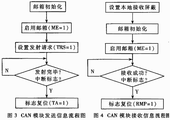
Figures 3 and 4 are flow charts of CAN module transmitting and receiving information, respectively.
As can be seen from the above introduction, TMS320F241 is a DSP chip dedicated to motor control and embedded with CAN module. It can easily realize the speed control of the permanent magnet brushless DC motor of the hybrid electric vehicle (HEV). At the same time, the embedded CAN module can be used to complete the hybrid vehicle through the CAN bus (protocol specification CAN2.0) The control unit (VCU) communicates. Therefore, it is very suitable for the control system of the permanent magnet brushless DC motor of the hybrid electric vehicle.
2 In 1 Laptop
Do you know the difference of Yoga Laptop and 2 in 1 laptop? No. 1 is yoga notebook with 360 flip rotating absolutely; No.2 is laptop yoga slim is just like normal Education Laptop-connecting screen with keyboard, but 2 in 1 laptop tablet with pen is separately, you can use the monitor part as a window tablet. In one word, every intel yoga laptop have all the features and function of tablet 2 in 1 laptop except separated screen and keyboard. From the cost, windows yoga laptop is much higher than 2 in 1 type., cause usually former with more complicated craft and quality.
What other products you mainly produce? It`s education laptop, Gaming Laptop, engineering laptop, Android Tablet, Mini PC and All In One PC. You can see more than 5 different designs on each series, believe always have right one meet your special application or your clients demands. Therefore, what you need to do is just to get all the requirement details from your clients, then share the complete information with us, then we can provide the most suitable situation.
Of course, you can also call or email or send inquiry of what you need, thus can get value information much quickly.
2 In 1 Laptop,2 In 1 Laptop Sale,2 In 1 Laptop Tablet With Pen,Tablet 2 In 1 Laptop,2 In 1 Laptop Deals
Henan Shuyi Electronics Co., Ltd. , https://www.shuyitablet.com