High temperatures can cause the probability of failure of electronic components to increase rapidly, resulting in a decrease in the reliability of LED displays. In order to control the temperature of the electronic components inside the LED display so that it does not exceed the specified maximum allowable temperature under the working environment under which the LED display is placed, the heat dissipation design of the LED display is required. The heat dissipation design of the LED display, how to achieve low cost and high quality, is the content of this article.
First, the knowledge of heat dissipation design
The two basic laws of heat transfer: heat flows from the high temperature zone to the low temperature zone; the heat generated by the high temperature zone is equal to the heat absorbed by the low temperature zone.
There are three basic ways of transferring heat: heat conduction, convection, and radiation.
Thermal conduction: Gas heat conduction is the result of collisions between gas molecules when they move irregularly. The heat conduction in the metal conductor is mainly achieved by the movement of free electrons. Thermal conduction in non-conductive solids is achieved by vibration of the lattice structure. The heat conduction mechanism in the liquid mainly depends on the action of elastic waves.
Convection: refers to the heat transfer process caused by the relative displacement between various parts of the fluid. Convection only occurs in the fluid and is necessarily accompanied by thermal conduction. The heat exchange process that occurs when fluid flows over the surface of an object is called convective heat transfer. The convection caused by the difference in density of the various parts of the fluid is called natural convection. If the motion of the fluid is caused by an external force (fan, etc.), it is called forced convection.
Radiation: The process by which an object transmits its ability in the form of electromagnetic waves is called thermal radiation. Radiant energy transfers energy in a vacuum and has a conversion in the form of energy, that is, thermal energy is converted into radiant energy and radiant energy is converted into thermal energy.
When selecting the heat dissipation method, the following factors should be considered: heat flux density, volume power density, total power consumption, surface area, volume, and working environment conditions (temperature, humidity, air pressure, dust, etc.) of the LED display.
According to the heat transfer mechanism, there are natural cooling, forced air cooling, direct liquid cooling, evaporative cooling, thermoelectric cooling, heat pipe heat transfer and other heat dissipation methods.
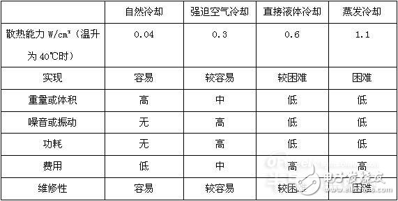
A comparison of several common cooling methods is as follows:

Natural cooling forced air cooling direct liquid cooling evaporative cooling
Heat dissipation capacity W/cm? (When temperature rise is 40 °C) 0.040.30.61.1
It is easier and harder to achieve
Weight or volume high, medium and low
No noise or vibration
No low or low power consumption
Low cost, high and high
Maintenance is easier and more difficult
It can be seen from the above table that the heat dissipation effect of natural cooling is relatively small, and the heat dissipation effect of evaporative cooling is relatively large. The human body sweats and cools down, using the heat dissipation method of evaporative cooling.
Second, the LED display heat dissipation design method
As can be seen from practical applications, the current LED display has more internal heat, and the electronic components with more heat are: LED, driver IC, and switching power supply. Therefore, it is necessary to heat-dissipate the LED display to provide a low thermal resistance path between the heat source and the external environment to ensure the smooth transfer of heat.
When the temperature of the object is lower than 1800 °C, the meaningful thermal radiation wavelength is between 0.38 and 100 μm, and most of the energy is in the range of 0.76~20μm in the infrared band. In the visible light band, the specific gravity of the thermal radiation energy is not large. Therefore, the interior of the LED display can be freely coated with various colors. The outside of the LED display that is exposed to direct sunlight should be painted in a light color to avoid visible light absorption.
Considering the use of the LED display screen, the rental screen and the indoor fixed installation screen mostly use the method of natural cooling and heat dissipation, and the outdoor fixed installation screen uses the method of forced air cooling to dissipate heat.
The LED display is fixedly installed outdoors, and the heat dissipation design should be considered when installing the entire screen. Due to the limitation of the installation location, as the power consumption of the LED display is reduced, more and more customers are naked in the LED display, and there is no other auxiliary cooling measures. For the large screen of the LED display, only the way of natural cooling and heat dissipation is relatively poor. Therefore, the heat dissipation design of the LED display box is particularly important. Considering the reliability and maintenance cost of the LED display box, it is a better way to dissipate heat by using a fan for forced convection cooling.
The heat exchange area between the heating electronic components and the cold air, the temperature difference between the heating electronic components and the cold air directly affects the heat dissipation effect. This involves the design of the air volume entering the LED display cabinet and the design of the air duct. When designing the ventilation duct, try to use straight pipeline to transport air to avoid the use of sharply bent and curved pipelines. Ventilation ducts should avoid sudden expansion or sudden contraction. Do not extend the angle of the opening more than 20? , the shrink cone angle should not be greater than 60? . Ventilation ducts should be sealed as much as possible, and all overlaps should follow the direction of flow.
There are several points to note when designing the LED display box: the air inlet should be placed on the underside of the cabinet, but not too low to prevent dirt and water from entering the cabinet installed on the ground. The venting holes should be placed close to the upper side of the cabinet. Air should circulate from the bottom of the cabinet, and a dedicated air inlet or vent should be used. Cooling air should flow through the hot electronic components while preventing short-circuiting of the airflow. A filter screen should be provided at the air inlet and outlet to prevent debris from entering the cabinet. Design should be such that natural convection helps to force convection. Be sure to keep the air intake and exhaust away from the design. Avoid reusing cooling air. Considering the factor of air volume expansion, the air outlet area should be 1.5 times to 2 times the air inlet area. Electronic components with large heat generation such as switching power supplies should be placed as close as possible to the air inlet. To ensure that the direction of the heat sink cogging is parallel to the wind direction, the heat sink slot cannot block the air path.
The fan is installed in the system. Due to structural constraints, the air inlet and outlet are often blocked and the performance curve changes. According to practical experience, the inlet and outlet of the fan should preferably be 40mm away from the barrier. If there is space limitation, it should be at least 20mm.
The selection of the fan is generally based on the size of the fan inlet and outlet air temperature. In the case of ventilation, since the fan draws hot air, it will have a serious impact on the life of the fan. For fan manufacturers, 60 °C is generally used as the condition for calibrating the fan life MTBF. If the ambient temperature of the fan application is higher than 60 °C, the fan life is reduced by half for every 5 °C increase in temperature.
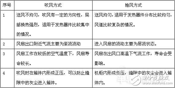
When considering the use of ventilation or air blowing, you can refer to the following table for comparison of air blowing and ventilation.

1 The air supply is uneven, the air blow has a certain directionality, and the local heat exchange is strong, which is suitable for the case where the heat generating device is concentrated. Uniform air supply, suitable for the distribution of heating devices is relatively uniform, the wind channel is more complicated.
2 The airflow near the fan outlet is mainly turbulent flow and the flow into the fan is mainly laminar.
3 The fan works at a lower air temperature and the fan has a longer life. The fan works at high airflow at the air outlet, and the life will be affected.
4 When the air blows, a positive pressure is formed in the box body to prevent dust in the gap from entering the box. A negative pressure is formed in the cabinet, and dust in the gap enters the cabinet.
The heat dissipation design of the module inside the box is also considered. Poor heat dissipation design will result in poor display performance and color spots. When placing the heating components on the PCB, consider the uniform distribution of heat as much as possible, and do not concentrate the components with more heat on a part of the PCB.
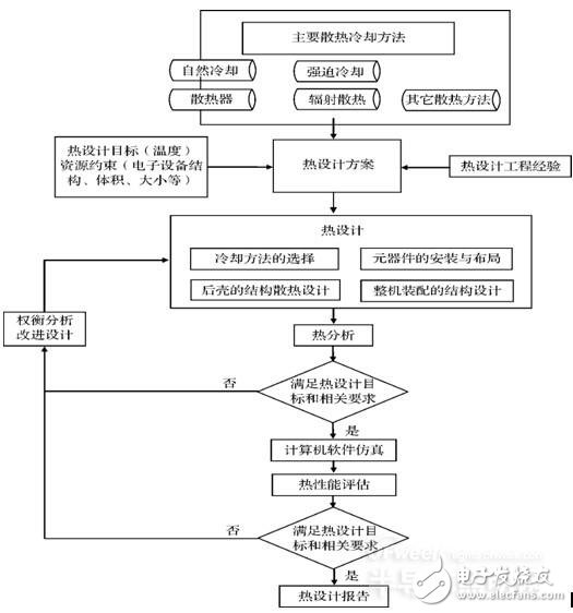
The following figure shows the flow chart of the heat dissipation design.

Early Ethernet
Megabit Ethernet
Xerox Ethernet (Xerox Ethernet, also known as "Xerox Ethernet") ─ ─ is the prototype of Ethernet. The original 2.94Mbit/s Ethernet was only used internally in Xerox. In 1982, Xerox, DEC and Intel formed the DIX alliance, and jointly published the Ethernet Version 2 (EV2) specifications, and put it into the market, and it is widely used. The EV2 network is currently 10BASE5 recognized by IEEE.
10BROAD36──It is outdated. An early standard supporting long-distance Ethernet. It is used on coaxial cable with a broadband modulation technology similar to a cable modem system.
1BASE5──It is also called a star LAN, and its rate is 1Mbit/s. It was a commercial failure, but it was also the first use of twisted pair.
10Mbps Ethernet
10BASE5 (also known as Thick Ethernet or yellow cable)-the earliest realization of 10 Mbit/s Ethernet. The early IEEE standard used a single RG-11 coaxial cable with a maximum distance of 500 meters, and can connect up to 100 computer transceivers, and both ends of the cable must be connected with a 50 ohm terminal resistor. The receiving end is inserted into the inner core and shielding layer of the cable through a so-called "plug-in tap". Use N-type connectors at the end of the cable. Although some systems are still in use due to a large number of early deployments, this standard was actually replaced by 10BASE2.
10BASE2 (also known as Thin Ethernet or analog network) ── products after 10BASE5, use RG-58 coaxial cable, the longest transmission distance is about 200 meters (actually 185 meters), only 30 computers can be connected The calculator uses a T-type adapter to connect to a network card with a BNC connector, and a 50-ohm terminator is required at both ends of the line. Although it is not as good as 10BASE5 in terms of capacity and specifications, it has been widely used because of its thinner wires, convenient wiring, and low cost, and it has eliminated 10BASE5. Due to the popularity of twisted pair, it has also been replaced by various twisted pair networks.
StarLAN-The first Ethernet standard 10 Mbit/s implemented on a twisted pair cable. Later developed into 10BASE-T.
10BASE-T── 4 wires (two pairs of twisted pairs) of Category 3 twisted pair, Category 4 twisted pair, and Category 5 twisted pair are used for 100 meters. An Ethernet hub or Ethernet Switch is located in the middle to connect all nodes.
FOIRL ──Optical fiber repeater link. Original version on fiber optic Ethernet.
10BASE-F ── 10Mbps Ethernet optical fiber standard generic name, 2 kilometers. Only 10BASE-FL is widely used.
10BASE-FL ── An upgrade to the FOIRL standard.
10BASE-FB ──The backbone network technology used to connect multiple Hubs or switches is obsolete.
10BASE-FP ──non-relay passive star network, there is no practical application case.
100Mbps Ethernet (Fast Ethernet)
See: Fast Ethernet
Fast Ethernet (Fast Ethernet) is an online standard published by IEEE in 1995, which can provide a transmission speed of up to 100Mbps.
100BASE-T-The following three 100 Mbit/s twisted-pair standards are generic names, and the maximum distance is 100 meters.
100BASE-TX-10BASE-T similar to the star structure. Two pairs of cables are used, but category 5 cables are required to achieve 100Mbit/s.
100BASE-T4 - Use Category 3 cables, use all 4 pairs of wires, half-duplex. Due to the popularity of Category 5 cables, it has been abandoned.
100BASE-T2 - No product. Use Category 3 cables. Supports full-duplex use of 2 pairs of wires, the function is equivalent to 100BASE-TX, but supports old cables.
100BASE-FX-- Uses multimode fiber, supports up to 400 meters, half-duplex connection (guaranteed collision detection), 2km full-duplex.
100VG AnyLAN - Only supported by HP, VG first appeared on the market. Need 4 pairs of Category 3 cables. Some people suspect that VG is not Ethernet. [2]
1Gbps Ethernet
1000BASE-T-1 Gbit/s medium super Category 5 twisted pair or Category 6 twisted pair.
1000BASE-SX-1 Gbit/s multimode fiber (depending on the frequency and fiber radius, the longest distance when using multimode fiber is between 220M and 550M).
1000BASE-LX-1 Gbit/s multimode fiber (less than 550M), single-mode fiber (less than 5000M).
1000BASE-LX10-1 Gbit/s single-mode fiber (less than 10KM). Long-distance program
1000BASE-LHX--1 Gbit/s single-mode fiber (10KM to 40KM). Long-distance program
1000BASE-ZX--1 Gbit/s single-mode fiber (40KM to 70KM). Long-distance program
1000BASE-CX--a short-distance (less than 25 m) solution up to 1Gbps on copper cables. Earlier than 1000BASE-T, it is obsolete.
10Gbps Ethernet
See: 10 Gigabit Ethernet
The new 10 Gigabit Ethernet standard includes 7 different types, which are applicable to local area networks, metropolitan area networks, and wide area networks. The additional standard IEEE 802.3ae is currently used and will be merged into the IEEE 802.3 standard in the future.
10GBASE-CX4 - Short-distance copper cable solution for InfiniBand4x connectors and CX4 cables, with a maximum length of 15 meters.
10GBASE-SR - used for short-distance multi-mode fiber, can reach 26-82 meters according to the cable type, and can reach 300 meters with the new 2GHz multi-mode fiber.
10GBASE-LX4 - Use wavelength division multiplexing to support 240-300 meters of multi-mode fiber and more than 10 kilometers of single-mode fiber.
10GBASE-LR and 10GBASE-ER - support 10km and 40km respectively through single-mode fiber
10GBASE-SW, 10GBASE-LW, 10GBASE-EW. Used for WAN PHY, OC-192/STM-64 synchronous optical network/SDH equipment. The physical layer corresponds to 10GBASE-SR, 10GBASE-LR and 10GBASE-ER respectively, so the same optical fiber supports the same distance. (No WAN PHY standard)
10GBASE-T-Use shielded or unshielded twisted pair, use CAT-6A cable to support at least 100 meters of transmission. CAT-6 cables also support 10GBASE-T over shorter distances.
100Gbps Ethernet
See: 100G Ethernet
The new 40G/100G Ethernet standard was formulated in 2010 and includes several different control types. The additional standard IEEE 802.3ba is currently used.
40GBASE-KR4 - Backplane solution, the minimum distance is 1 meter.
40GBASE-CR4 / 100GBASE-CR10 - Short-distance copper cable solution, the maximum length is about 7 meters.
40GBASE-SR4 / 100GBASE-SR10 - used for short-distance multimode fiber, the length is at least 100 meters.
40GBASE-LR4 / 100GBASE-LR10 - Use single-mode fiber for distances over 10 kilometers.
100GBASE-ER4 - Use single-mode fiber for a distance of more than 40 kilometers.
Ethernet Poe Onu,POE Power Supply Function,POE ONT,POE ONU
Shenzhen GL-COM Technology CO.,LTD. , https://www.szglcom.com