1. Main components
One LM324, 74HC00, NE555, one voice/music piece, one speaker, φ3 infrared LED. Three φ3 infrared phototransistors and resistors and capacitors. The phototransistor has high sensitivity and is suitable for photoelectric remote control; the photodiode has low sensitivity and high bandwidth, and is suitable for communication. The integrated IR receiver operates at a fixed frequency of 38 kHz. The design selects the frequency to be 5 kHz in the single-channel warning, and the selection frequency is 3.3 kHz/5 kHz in the dual-channel warning. The 38 kHz fixed working frequency cannot meet the multi-path requirement, so the integrated infrared receiving head is not selected.
2. The selection of the working frequency is caused by the incandescent lamp and the fluorescent lamp. The interference generated by the fluorescent lamp is low frequency signal, and the remote control is 38-40 kHz. Therefore, the operating frequency of the alarm device is set to 5kHZ and 3kHz, which can be far away from interference, and is also beneficial for testing with an ordinary pointer type multimeter AC gear. In addition, experiments have shown that the sensitivity of the phototransistor at 5 kHz, frequency F, maximum load of 10kΩ ~ 20kΩ, higher sensitivity, if the frequency is reduced, the load resistance can not be increased due to stray background light, sensitivity can not continue to improve.
If the frequency is raised to 20 kHz, the charge and discharge speed of the phototransistor of 20kΩ load can not keep up, the signal is attenuated, and the load resistance must be reduced to 1kΩ~2kΩ to increase the charge and discharge speed, so the sensitivity is reduced by 10 times. In addition, 20kHz amplifiers are also difficult to do.

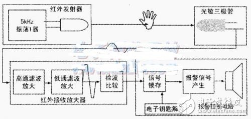
As shown in the figure below, the infrared transmitting tube emits a beam of light to reach the remote receiving tube. When the centers of the two tubes are opposite, an AC signal of about 1 mV and 5 kHz is generated. After high-pass filtering amplification, the 50-100 Hz interference signal is attenuated from the normal signal. More than 10,000 times. After low-pass filtering amplification, the 40kHz interference signal is attenuated several hundred times more than the normal signal, and the 5kHz signal is amplified to nearly 2000 times. At this time, the signal exceeds the linear amplification range of the amplifier and is limited to a ladder wave. The DC voltage of the detected output exceeds 2V. This voltage is compared with the undetermined voltage Vf. If it is greater than Vf. It is considered that the illumination is normal and does not alarm. If it is less than Vf, it indicates that there is an object blocking light and the alarm control circuit is activated. The condition of the alarm is: the electronic key does not exist, the mouse light normally occurs too low, the signal is latched, and the drive/music piece alarms. Once the electronic key is inserted, the signal latch is reset, and the alarm is disabled, which is suitable for the activities of the person. This design leaves a margin on both the magnification and the setpoint set voltage. You can also choose different alarm music pieces and make different electronic keys to give your readers the freedom to play.
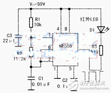
4. Working principle analysis(1) Infrared emitter infrared emitter circuit is shown below. The time base circuit NF555 is connected to a self-excited oscillator, and its 2-pin 6-pin triangular wave varies between 1/3VCC and 2/3Vcc. When the voltages of pins 2 and 6 are 1.3Vcc, Vcc charges C1 through R1 and R2, and the high level is output in pin 3. After 0.693 (R1 + R2) C1 time, the voltage of 2 and 6 feet rises to 2/3Vcc. At this time, the output of the 3 pin is turned to a low level, the 7 pin is turned on to the ground, and C1 is discharged through R2, after 0.693 & TImes; At R2C1 time, the voltage of pins 2 and 6 drops to 1/3Vcc, and the 3 pin outputs high level again. As can be seen in the figure, the 3-pin output high-level time is long, and the output low-level time short cycle is the sum of the two. In this example, when R2 is 11.2kn, the measured frequency is just 5kHz. The driving power of the NE5553 pin is very strong. In this example, R3=510n, there is a low-level current of 15mA to drive the LED. If you want to further enhance the launch, you can reduce R3 to 270Ω.

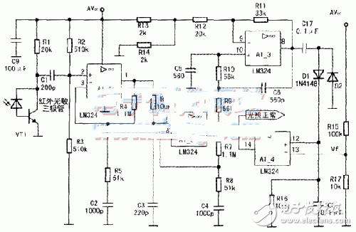
(2) Infrared Receiver Amplifier The infrared receiver amplifier circuit is shown below. After VT1 is received, the output signal voltage is 1mV, and C1, R2, and R3 form the first-stage high-pass filter. So, how are the parameters of C1, R2, and R3 derived? It is based on experience. For AC signals, R2 and R3 are connected in parallel with an equivalent resistance of approximately 250kΩ. If the capacitive reactance of C1 at a certain frequency is equal to 250k, the signal is attenuated to 70%. If you want most of the 5kHz signal to pass, the signal starts to decay at 5kHz & TImes; 70% = 3.5kHz. You only need to remember the capacitive reactance of 160kQ of 10kHZ100pF capacitor, frequency ÷2=5k, capacitance &TImes; 2=200p, the capacitive reactance is unchanged. , still 160kΩ. The frequency is further reduced by 70%, the capacitive reactance is increased by l/70%, which is about 230kΩ, and the frequency is lower to meet the requirement. Let C1 use 200pF and the 70% attenuation point is about 3.2kHz. R4, R5, and C2 introduce a second-level high-pass in the feedback loop. When the frequency is high, C2 is approximately short-circuited, the amplification factor is 1+R5/R4, about 22.5 times; when the frequency is very low, C2 is not connected, and 1 foot l00% is negatively fed back to 2 feet, and the magnification is 1. The capacitive reactance of C2 is compared with that of R5. Applying the calculation just now, the capacitance is increased by 5 times, 100Op is taken, and the resistance of 250kΩ is reduced by 5 times, taking 51kΩ. The measured first stage is amplified 19 times at 5 kHz, the 3 kHz signal is attenuated by more than 50%, and the 100 Hz signal is barely visible. R6 and C3 form a low-pass filter, taking 1.4 times 7kHz of 5kHz as the attenuation point. It is known that the capacitive reactance of 10kHZ100pF capacitor is 160kΩ, the capacitive reactance of 7kHZ100pF capacitor is 160kΩ, /0.7=224kΩ, and the capacitance of 220pF capacitor is reduced by 100pF. 2.2 times, 100kΩ, so the values ​​of R6 and C3 are 100kΩ and 220pF, respectively. R7, R8, and C4 form a high-pass filter, which is identical to R4, R5, and C2. The measured first and second levels are amplified by 300 times at 5 kHz, and the third stage LM324 amplification task is 6 to 7 times, and the total multiple is 2000 times. This is a second-order low-pass filter with C6 positive feedback. The peak point requires 5 kHz, the peak impedance is equal to the impedance at the peak point, and the positive feedback coefficient is 1/3. It is known that the capacitive reactance of a 10kHZ100pF capacitor is 160kΩ, and the capacitive reactance of 50kHZ100pF is doubled to 320kΩ. The capacitance of the 5kHz 560pF capacitor is multiplied by 5.6 times to 57kΩ and 56kΩ. R1l, R12+R13//R14 constitute negative feedback, and the DC amplification factor must be limited to 3 or less, and more than 3 will self-oscillate. Here, the DC amplification factor is 2.57, and the measured total magnification of 5 kHz is 1920 times. The output of the third stage amplifier is coupled through C7, and D1 and D2 are detected, and a DC voltage is formed on R16. When there is no signal, the noise will also have a detection voltage, but much smaller. The fourth stage LM324 is connected to the comparator mode. The detection voltage is compared with the R15/R17 divided voltage Vf. The detection voltage greatly exceeds Vf, and the output high level is about 3.5V, indicating that the "light is normal". The transmitted signal is blocked and the output is low level of approximately 1.5V. In the figure below, AVce is connected to 5V.

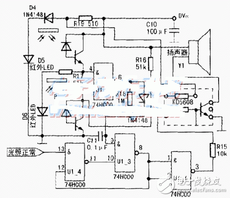
(3) The alarm control circuit is shown in the figure below, in which DVcc is connected to AVcc and connected to +5v. U1_4 and U1_3 form a latch. When normal (that is, when the light is normal), the (13) and (12) pins are all high level, (11) and (10) are low level, and 8 feet output high level. U1-l is used as an inverter, and 3 pins output low level, U2 does not work. When the "normal light" signal disappears, the (13) pin goes low, the U1_4 (11) pin goes high, the U1_38 pin goes low, and the U1_4 (12) pin is also low. That is to say, no matter whether the "Lighting normal" signal is there or not, the case that was once low will be latched, the U1_3 output 8 pin is always low, the U1-13 pin output is high, and the alarm music piece KD5608 is driven to make a barking sound. Readers are also free to play and create different alarm effects.
The two input terminals of U1_2 are connected to two phototransistors, one pull-up and one pull-down. Because working in the dark, the load resistance can be taken larger to increase sensitivity. Regardless of whether there is full illumination or no illumination, there is always one input low for U1_2 and a high output for 6 pins. It is best to set the background A to be black and the background B to be white so that the 4 and 5 feet are low. The electronic key can be made into a perforated light transmission type, or it can be painted in a black and black reflective type. Once A has light B and no light (ie, the electronic key is inserted), U1_2 has 4 and 5 feet high, and 6 feet output is low. After delaying O.ls, the 9th pin of U1_3 continues to be low, and the 8th pin is always high. No matter whether the "normal illumination" signal is present or not, it can not alarm and establish the initial state of U14 (12) pin high. The design of the electronic key can be varied, and it is not limited to the two logical points of A and B, and can be creative.
The forward voltage drop of D4, D5 and D6 is 3V, which is just for U2KD5608 (3V). Note: Many music pieces are misused by the SV power supply, causing the sound to be wrong and the chip to heat up. Pay attention to the buck. But the speaker can be connected to a 5V power supply.
The high level of the control signal output from the U1_3 pin is also SV. In order to avoid damage to U2, a resistor R15 is connected in series.

SHENZHEN CHONDEKUAI TECHNOLOGY CO.LTD , https://www.szfourinone.com