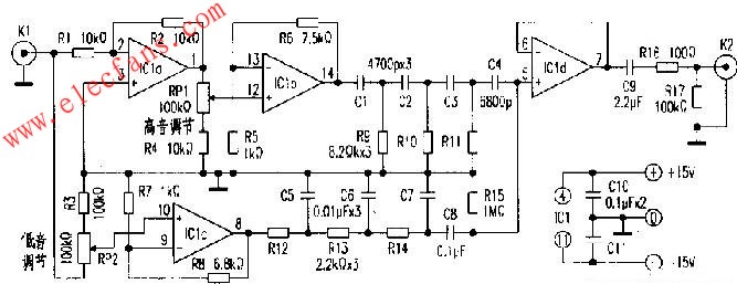
The inverted tone control circuit is shown above. IClb and IClc are high-pitched signal and bass signal inverting buffer amplifiers, respectively. RPl and RP2 respectively adjust the signal level of the input high and low frequency inverting buffer amplifier, and the inverting amplifier circuit withstands the maximum undistorted AC signal as lV. Cl, C2, C3, R9, R10, and R11 form a high-tone network, and C5, C6, C7, R12, R13, and R14 form a low-tone network. In order to compensate for the large attenuation of the high audio segment signal by the high audio response network. In order to maintain the balance of high and low audio, the ICla preamplifier circuit is added. If the resistance values ​​of R3 and R4 are appropriately reduced. It can increase the amplitude adjustment range of the intersection of high and low frequency network frequency response characteristics. The resistance value shown in the circuit diagram, the amplitude adjustment range is about 20dB. The coupling capacitors C4 and C8 respectively output the inverted high- and low-frequency audio signals, and are mixed and applied to the load resistor R15, and are incident on the amplifier ICld. Then, it is output through the DC blocking capacitor C9 and the capacitive load current limiting resistor R16. R17 acts as a stable output DC at OV potential. In order to keep the gain of each stage amplifier consistent. The circuit uses TL074 four arithmetic integrated amplifier.
This article refers to the address: http://

The frequency chart of RP1 and RP2 is adjusted to the minimum value, the intermediate value, and the maximum position, respectively. When both potentiometers are placed in the middle position. The high and low audio response characteristics swing slightly above and below the 0dB benefit, close to a flat line.

Residential Energy Storage System
electricity backup for home,5kw solar system,solar for home,house backup power supply,15kw solar system,off grid life
EMoreShare International Trade (Suzhou) Co., Ltd , https://www.emoresharesystem.com