RF system engineers often use simple and rude methods to handle these effects, such as inserting an attenuator or isolation amplifier before and after a sensitive device. It is well known that these methods reduce the signal-to-noise ratio and dynamic range of the entire system. We can use the port of the duplexer to achieve the absorption of the stopband reflection signal, but such a transition means has a large space requirement for the design circuit, and still causes impedance mismatch due to some reflected signals. Of course, we can also use a differential filter (two ports into the two ports, and add a 90 ° bridge to the input and output ports to achieve balanced - unbalanced conversion) to mitigate the effects of the stopband reflected signal. But this technique makes the bandwidth of the filter subject to the bandwidth of the bridge, which makes this design unsuitable for broadband applications.
In order to eliminate the true and ubiquitous reflected signals in the filter stopband, Mini-Circuits has developed the X-Series non-reflective filter (patented). This family of filters features a new filter architecture that fully sinks or terminates all of the internal stopband signals that are unwanted through the filter, achieving a reflection coefficient of zero at all frequencies.
Principle: Minimized reflection coefficient improves system dynamic range
In circuit design, for the problems often caused by conventional reflective filters, non-reflective filters are particularly suitable for pairing sensitive nonlinear devices. A typical case, such as the application of a filter on the output signal link of a mixer. The mixer produces a large amount of unwanted mixing signals, higher harmonics from the local oscillator, and other unwanted frequency signals, which must be filtered out. However, the use of conventionally designed filters may cause these signals to be reflected back into the mixer for re-conversion or new mixing with the wanted signal, resulting in a large number of unexpected unwanted signals. And it is likely that these unwanted signals are just inside the filter passband and cannot be filtered out.
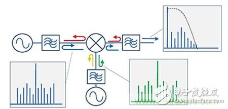
Figure 1. Typical intermodulation excess produced by reflection from multiple filters
Intermodulation suppression has always been one of the goals of mixer design. Based on the current development of the semiconductor industry, we can successfully achieve different levels of intermodulation suppression by using high dynamic range FETs. However, even the best mixers produce some intermodulation products at each of its ports, and these intermodulation products can be a factor in the surrounding RF link. When traditional filters filter out these intermodulation products, they are completely reflected back to the mixer and resynthesized with the fundamental signal to produce a large number of spurious signals. These spurious signals are output to the intermediate frequency through the filter because they may fall within the required frequency band, thereby limiting the dynamic range of the entire system.
If the out-of-band reflection coefficient of the filter is minimized, the unwanted signals reflected back will be reduced, and the false signals and intermodulation products will be reduced, thereby improving the dynamic range of the entire system.
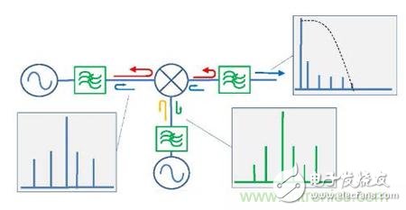
Figure 2 Reduced out-of-band reflection signal and thus reduced intermodulation products
Theoretical verification
The performance of the test mixer is compared to the traditional mixer and the non-reflective filter respectively paired with the same mixer.
Test 1: IF signal output spectrum test for single input signal
According to the test circuit shown in Figure 3, the signal spectrum reflected from the filter to the mixer output in three different states will be tested:
State 1: The mixer output port is directly output;
State 2: Mixer output port plus conventional filter;
State 3: Mixer output port plus no reflection filter.
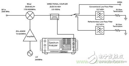
Figure 3 IF signal output spectrum test circuit block diagram of single input signal
The test results for each state are shown in Figures 4-6. Compared to the direct output of the mixer, the addition of a conventional filter can reduce the reflected signal to some extent, while the non-reflective filter almost eliminates all reflections. From the results plot we can see that at 2 GHz, the reflected signal using a conventional filter is -34.55 dBm, while the non-reflective filter is -66.12 dBm. In contrast, the reflected signal is reduced by more than 30 dB. The reflected signals at other frequencies are also suppressed and filtered by the non-reflective filter.
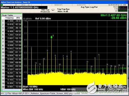
Figure 4 mixer direct output
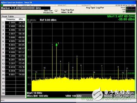
Figure 5 Output after mixing the mixer with a conventional filter
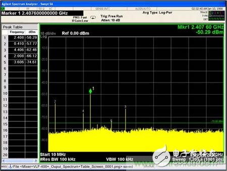
Figure 6 Output after mixer plus non-reflective filter
Test 2: Input spectrum test for single input signals
According to the test circuit shown in Figure 7, the signal spectrum reflected from the mixer to the source in three different states will be tested:
State 1: The input signal is directly input to the mixer;
State 2: The input signal is input to the mixer after passing through a conventional filter;
State 3: The input signal is passed through the non-reflective filter and input to the mixer.
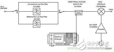
Figure 7 Input spectrum test circuit block diagram of single input signal
KNL5-63 Residual Current Circuit Breaker
KNL5-63 Moulded Case Circuit Breaker is MCCB , How to select good Molded Case Circuit Breaker suppliers? Korlen electric is your first choice. All moulded Case Circuit Breakers pass the CE.CB.SEMKO.SIRIM etc. Certificates.
Moulded Case Circuit Breaker /MCCB can be used to distribute electric power and protect power equipment against overload and short-current, and can change the circuit and start motor infrequently. The application of Moulded Case Circuit Breaker /MCCB is industrial.
Korlen electric also provide Miniature Circuit Breaker /MCB. Residual Current Circuit Breaker /RCCB. RCBO. Led light and so on .
KNL5-63 Molded Case Circuit Breaker,Small Size Molded Case Circuit Breaker,Electrical Molded Case Circuit Breaker,Automatic Molded Case Circuit Breaker
Wenzhou Korlen Electric Appliances Co., Ltd. , https://www.zjmotorstarter.com