With the rapid development of building automation and lighting industry, traditional lighting control is gradually replaced by intelligent control. DALI, as a new intelligent lighting control protocol, defines the communication mode between electronic ballast and controller to realize intelligent lighting system. Automation control, then, how to quickly debug the DALI protocol for lighting control?
First, DALI introductionThe DALI Digital Addressable LighTIng Interface ballast is the latest dimmable fluorescent Lamp ballast. DALI is a data transmission protocol that defines the communication between electronic ballasts and device controllers. The system based on DALI protocol has distributed intelligent modules. Each intelligent DALI module has digital control and digital communication capabilities. , address and lighting scene information are stored in the memory of each DALI module. The DALI module performs digital communication, command and status information through the DALI bus, and realizes functions such as lamp switching, dimming control, and system setting. The DALI bus develops a lighting control system with simple system structure, convenient installation, easy operation and excellent functions. It can be used for lighting control in a room, and can also connect more advanced equipment networks, such as Ethernet, to support more devices. And enough network bandwidth. The basic parameters of the DALI protocol are as follows:
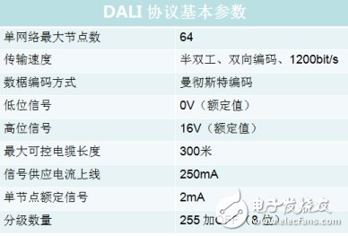
Figure 1 Basic parameters of the DALI protocol
The DALI bus is mainly used for dimming control of multiple fluorescent lamps and LED lighting. Each ballast can be individually addressed by a dimming controller. 64 single ballasts can be individually addressed on a single DALI number control line. Each ballast can be set with 16 lighting scenes. A ballast can also be programmed in one or more groups with a maximum number of groups of 16, which means that a DALI system can control up to 1000 ballasts.
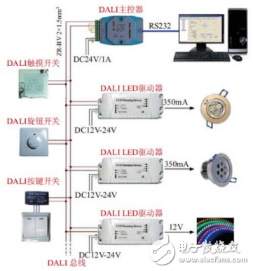
Figure 2 DALI system structure
Second, DALI digital frame structureDALI uses two-way Manchester coding, and the values ​​"1" and "0" indicate two different levels of transition. The transition from a logic low level to a high level indicates "1", and a transition from a logic high level to a low level indicates "0."
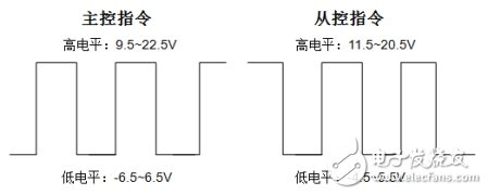
Figure 3 DALI level standard diagram
DALI data is divided into two categories: forward frame and backward frame. The transmission direction of the forward frame is from the main control unit to the slave control unit, consisting of 19 bits, including 1 bit start bit, 8 bit address bit, 8 bit data bit and 2 bit stop bit, as shown in Fig. 4;

Figure 4 DALI forward frame structure
· Start bit: logic value "1" as the start bit
· Address bits: 8-bit address bits can be used to communicate between electronic ballasts in the system. Individual addresses of individual slaves can be individually controlled. The addressing range is from O to 63, which can control 64 different addresses. Short address; DALI controller has group control group address command, the addressing range is 0-15, and up to 16 groups of group control can be performed.
· Digital clamp: The function of forward and reverse transmission of information of 8-bit data bits, including control information such as on/off lamp, dimming and dimming time of the lamp.
· End bit: Two non-coded high levels.
The transmission direction of the backward frame is from the slave control unit to the master control unit. In the DALI protocol, the slave sends data to the host only when the master controller queries. The data transmitted from the slave to the master consists of 11 bits of data. The first bit is the start bit, the second to the 9th bits are the data bits, and the 10th bit and the 11th bit are the stop bits. As shown in Figure 5.

Figure 5 DALI backward frame structure
Third, the actual application and analysisOn-site analog lighting control DALI communication protocol, here is the data mining oscilloscope ZDS4054 Plus as an example, its free standard DALI decoding function, can decode the full memory 512Mpts data, and between the lighting controller and the ballast Signal monitoring, taking information of one frame of data is viewed in the event table, as shown in Figure 6 below:
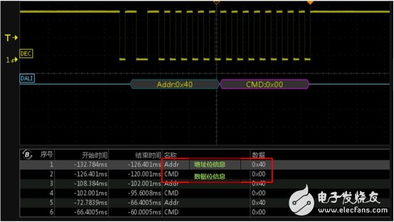
Figure 6 DALI protocol decoding interface
Perform anomaly analysis on long-term monitoring data, and use the dual ZOOM multi-window display function in the zoom mode of the oscilloscope to perform multi-window abnormality monitoring and analysis on the signal, and can simultaneously raise the rising edge of any data frame and several frames. The falling edge details are analyzed, and then by looking at the details of the enlargement, the data in the event table and the waveform are in one-to-one correspondence, and the positioning abnormality is very convenient, as shown in FIG. 7 below.
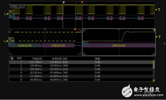
Figure 7 details analysis
Fourth, summaryZDS4054Plus oscilloscope is equipped with DALI protocol free of charge. Based on 512Mpts memory depth, it can perform long-term monitoring and decoding of lighting control DALI communication, and support DALI protocol triggering. At the same time, waveform details can be analyzed through oscilloscope rich plug-ins and abnormal search methods. problem.
Available Usb Receiver Mouse,Wireless Mouse Bluetooth,Office Pc Bluetooth,Pc General Purpose Bluetooth
Guangzhou Lufeng Electronic Technology Co. , Ltd. , https://www.lufengelectronics.com