The most common method of doing charging pile protocol testing today is to use a real vehicle for verification testing. However, this method has many drawbacks. Here we will introduce a solution for the BMS simulation system built by the split device.
This article refers to the address: http://
1.1 The drawbacks of real vehicle testing
· Not representative: There are still differences in the BMS communication protocols between mainstream electric vehicles on the market, and it is difficult to find a representative model.
· Only functional verification can be performed: The actual vehicle test can only verify whether the charging pile can be charged. It is not known whether it is strictly in compliance with the national standard 27930-2015.
· Long discharge time: After using the real vehicle for a long time, the battery of the electric vehicle will be full and it will take a long electricity process to discharge.

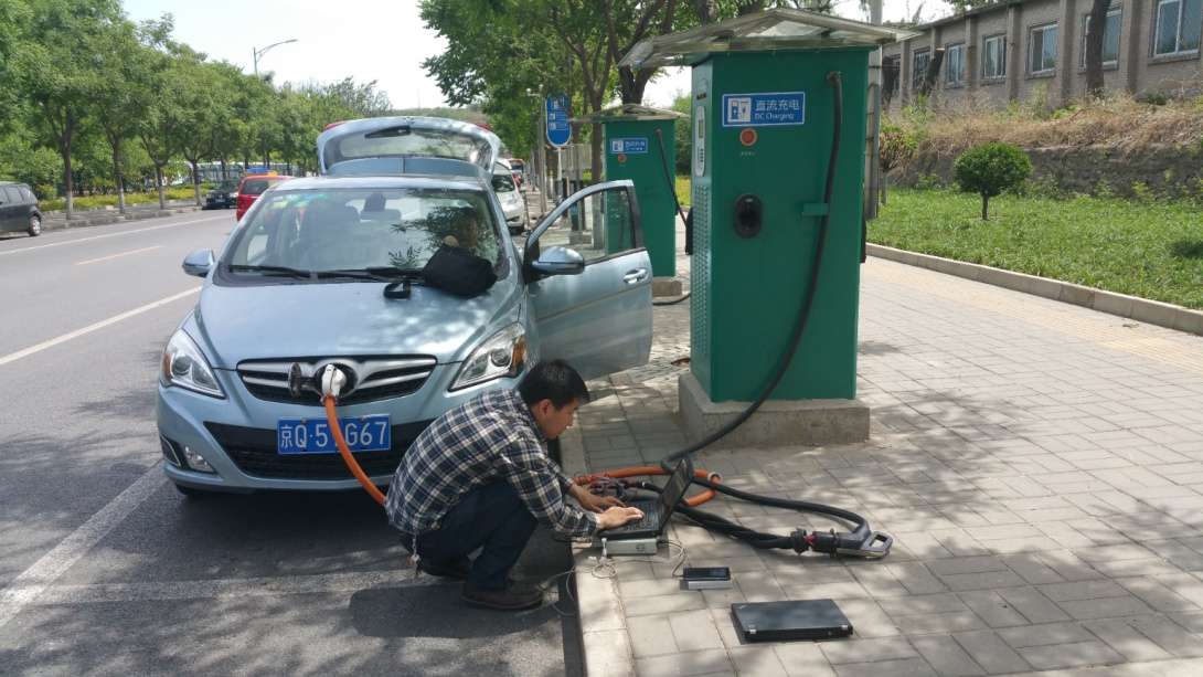
Figure 1 Charging station communication protocol verification using real vehicle
1.2 BMS simulation system construction
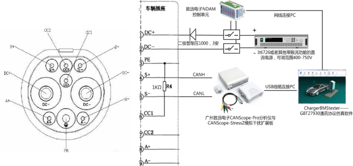
In order to avoid the above problems caused by real vehicle testing, we can build a BMS simulation system by ourselves. The system consists of the following types of equipment.
· Protocol Simulator: It is used to simulate the BMS message and the charging pile in the national standard 27930-2015. Here, the CANScope of Zhiyuan Electronics is taken as an example. It not only has the function of the protocol simulator, but also can synchronously perform protocol consistency detection and fault simulation. Complex functions such as signal quality assessment.
· Voltage Simulator: Connected to the charging piles DC+ and DC-, and strobed through the relay to simulate the battery voltage. In the national standard 27930-2015, it is mentioned that in the charging configuration stage, the charging pile needs to detect that the vehicle terminal battery voltage is normal before entering the charging phase, otherwise the charging will be stopped. Any DC power source that can output the maximum and minimum voltage of the charger can be used.
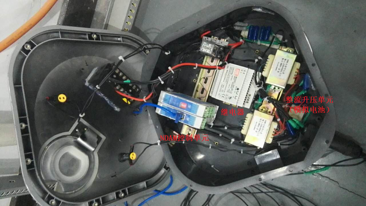
· K5, K6 control unit: drive the above relay, cooperate with the protocol simulator, realize the relay pull-in when the charging process enters the charging configuration stage, and then the charging pile detects the analog battery voltage. This paper recommends the selection of the control unit consisting of NDAM-9000 and NDAM-2808 from Zhiyuan Electronics, which can be linked with CANScope through the network port.

Figure 2 BMS simulation system block diagram

Figure 3 BMS simulation system physical map
1.3 Operation process
· Connect the device to the charging post according to the system block diagram.
· Adjust the voltage simulator to output a constant voltage. The output voltage is between the maximum output voltage and the minimum output voltage of the measured charging post.
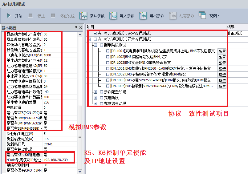
· Start CANScope's charging pile protocol conformance test software ChargerBMS_Tester, select BMS simulation test, configure the corresponding information mainly including analog BMS parameters, K5, K6 control unit enable and IP address settings.
· Check the test items that need to be started to start the test.

Figure 4 software settings
SWITCH SOCKET
Guangdong Shunde Langzhi Trading CO., Ltd , https://www.langzhielectrical.com