The arrangement of the LEDs and the specification of the LED source determine the basic driver requirements.
The main function of the LED driver is to limit the current flowing through the LED under certain operating conditions, regardless of the input and output voltage changes. The most common is the use of transformers for electrical isolation. The dimming factors that LED lighting design needs to consider are discussed below.
It is precisely because of the requirements of dimming that driving LEDs faces many challenges. For example, the forward voltage will change with temperature and current, and the LED forward voltage of different individuals, different batches, and different suppliers will also have The difference; in addition, the "color point" of the LED will also drift as the current and temperature change.
In the following, the LEDs are connected in series, and the power supply is 12V, so a booster circuit is used.
1. System composition
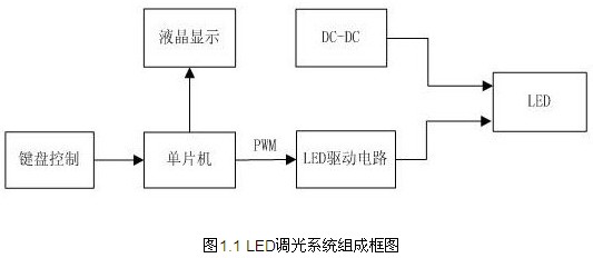
The block diagram of the LED dimming system is shown in Figure 1.1.

2. Design of unit hardware circuit
2.1 MAX1771 based boost (Boost) circuit
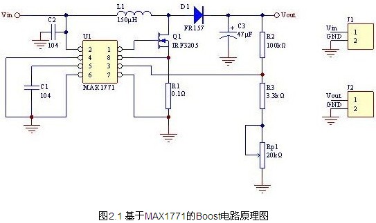
The MAX1771 is a power management chip from Maxim. It can be used as a booster circuit. The circuit structure is a Boost circuit, as shown in Figure 2.1 below. When the voltage input voltage ranges from 5 to 12V, the output is adjusted according to the range of 24-36V. Pin 1 outputs PWM to control the turn-on and turn-off of the FET IRF3205. Pin 3 is a voltage feedback terminal with a built-in 1.25V regulated supply. When the voltage input to pin 3 is higher or lower than 1.25V, the chip will automatically adjust the PWM duty cycle to decrease or increase to obtain a stable output.
