In recent years, medical devices have been moving toward smaller and smaller trends; small implantable devices can make patients feel more comfortable and have less disturbance to the body during implantation. In order to meet the demand for smaller hybrid components in implantable medical devices, hybrid microcontrollers (MCUs) or application specific integrated circuits (ASICs) and hybrid layout and packaging technologies for power systems are constantly being improved. This article explores the selection process for passive components with the goal of reducing the mix of components and board space in medical devices.
introduction
Passive components are produced in large-scale manufacturing facilities and have excellent process control to reduce differences between batches. Compared to commercial components, medical components require higher levels of reliability and performance in a smaller size. In the component manufacturing method, various solutions can be taken to reduce the space occupied by the hybrid components and the circuit board, and at the same time improve reliability.
Capacitor selection standard
Each capacitor technology has its own unique attributes that should be considered as part of a specific reference standard when selecting a product for the final application.
Multilayer ceramic capacitor (MLCC) for implantable devices with a housing size of 0201 (0.024 in & TImes; 0.012 in) for decoupling or tuning functions for radio/telemetry systems. The largest MLCC size is 2225 (0.22 in & TImes; 0.25 in), which is commonly used as a resonant capacitor for in vitro medical devices.
The size of the solid tantalum capacitor for medical devices is 0402 (0.045 in & TImes; 0.026 in & TImes; 0.024 in), and its low height helps to save space. In addition, there is a reliable, high-capacity solid tantalum capacitor with a 1210 T case size (0.138 in x 0.11 in x 0.063 in).

Silicon-based capacitors have been introduced in sizes of 20 mil x 20 mil and a maximum capacitance of 1000 pF. Silicon capacitors can be bonded by epoxy or eutectic chips and are wire-bonded. There is also a surface mount "flip-chip" silicon-based capacitor with a 0402 case size and a maximum capacitance of 27pF. Silicon-based capacitor technology supports reliable wideband operation (20 GHz) with high Q, low DC resistance (DCR) and high self-resonant frequency (SRF).
Magnetic component selection standard
Most magnetic components are custom designed to fit the limited space of a particular medical device application, by a collaboration between a medical device manufacturer and an engineer at a magnetic component company. Magnetic components tailored for implantable devices typically consist of a skeletal transformer, a toroidal coil transformer, a molded inductor, and an antenna with unique properties and shapes. In addition, a wide variety of core materials and shape optimization properties can be used to meet the needs of different applications.
After discussing the trade-offs in size, price, and performance, you can target the most cost-effective and best-performing components that match your space requirements. Once the design work is completed, rigorous manufacturing processes, controls, and testing procedures can be established to ensure the highest quality levels and optimal reliability in terms of size and magnetic performance. Small designs often require 3D CAD simulation to achieve accurate component placement and prototyping.
A variety of special air-core coils, bobbins and toroidal coil winding equipment are used in the manufacture of custom magnetic components. This equipment has critically controlled critical electrical performance requirements. Measurements of critical dimensions use inspection equipment such as optical measuring instruments. Custom designed test benches and fixtures monitor and test electrical parameters. Data analysis can be performed using these automated test benches to ensure design manufacturability.
The size and shape of the magnetic components used in different medical devices vary widely, depending on the specific application scenario. The 0402 small size inductor (0.040in x 0.020in) is used for telemetry/communication applications. These inductors can be wire-wired and made of ceramic cores with a maximum inductance of 150nH.
The high frequency wire-wound RF spiral inductor is available in two sizes: (0.030in × 0.030in × 0.020in) and (0.050in × 0.050in × 0.020in). These inductors excel in the RF band and are suitable for bias, tuning, and lumped component filter applications.
Resistor selection standard
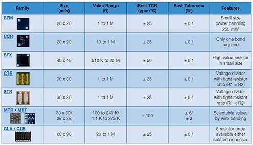
Standard film and thick film surface mount resistors have housing sizes between 0402 and 2512. Resistor selection criteria include pulse processing capability, operating voltage, operating temperature, and long-term stability. Wire-wound resistors range in size from 0.015in × 0.015in × 0.010in (rated power 125mW) to 0.055in × 0.055in × 0.010in (maximum resistance is 30MΩ; operating voltage is 100V).

Thin film resistors support dense circuit layout while providing the advantages of a highly reliable resistor film. Resistor tolerances as low as 0.01% and temperature coefficient of resistance (TCR) as low as 5ppm facilitate accurate tuning of amplifiers, transceiver circuits and power distribution. For medical applications, these chip resistors can cover any standard resistance value (10Ω~25MΩ).
High reliability test
For medical device applications, avoiding catastrophic failure and drift failure of passive components is a top priority. Ultimately, product reliability predictions are based on supplier test data and application operating temperatures specified by the medical device manufacturer over a defined time frame. Process control by passive component suppliers is an important factor in achieving high reliability. By raising the temperature at rated or higher voltages and performing life tests for specified durations, the reliability of passive components can be determined and components can be used for critical medical device applications. Passive component testing is based on customer requirements and US Military Standards (MIL) specifications, if applicable.
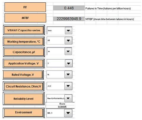
Reliability prediction of passive components can be performed using an online modeling program based on the MIL-217 manual or IEC863. The following is a vendor reliability simulation example

The solid-state test standard is based on MIL-PRF-55365. Solid-state capacitors undergo internal qualification and periodic maintenance tests at elevated temperatures and voltages. For critical applications, tantalum capacitors are designed, manufactured, and tested to meet customer-customized limits.
The table below shows the failure rate prediction based on the Weibull test of the solid tantalum capacitor.

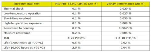
Qualified tests for resistors for critical medical applications are performed in accordance with MIL-PRF-55342. Resistor failures fall into two categories: fatal failures (eg, open or shorted resistors) and drift failures (resulting in poor circuit operation).
The measured resistor performance can be compared to the MIL-PRF-55342 limits as shown in the table below.

The internal reliability test for custom magnetic components is based on the MIL-PRF-27 standard. The tests conducted included solderability, solvent resistance, terminal strength, impact and vibration, moisture resistance, and thermal shock. These tests are detailed in MIL-STD-202 and other ASTM or JEDEC standards.
to sum up
With small medical equipment, surgery can be made simpler and less invasive, making it easier for doctors to operate and alleviate patient suffering. With the introduction of smaller and newer passive components, there is a corresponding need for better manufacturing and testing techniques to improve component quality. Suppliers of new small-sized passive components may need to increase their equipment and automation inputs to achieve the process capabilities required by medical device manufacturers. Qualified testing and reliability testing in accordance with customer requirements and industry standards are requirements of the development process.
Heat Shrink Tubing, also known as heat shrinkable protection tubing, provides insulation protection for wires, cables and wire terminals. With high temperature shrinkage, soft flame retardant, insulation and corrosion protection, etc., it is widely used for insulation protection of various wiring harnesses, solder joints, inductors, and rust and corrosion protection of metal tubes and bars. Heat Shrink Tube flame retardant, insulation, temperature resistance, heat shrinkable tubing is a special polyolefin material heat shrinkable tubing, also called EVA material. It is soft and flexible. Heat (125 degrees) will shrink, widely used in a variety of harnesses, solder joints, inductors, insulation protection, metal tubes, bars, rust, corrosion. Commonly used in the wire connector, choose the right heat shrink tubing, set on the wire connector, heated with a hot air gun, the heat shrink tubing contraction, the connector set firmly. Can be used for general electronics, electrical appliances, batteries and other packaging insulation. Through the use of heaters can be made to tighten, play insulation, protection and other functions.
Non-slip Heat Shrink Tube,Heat Shrink Tube,Silicone Heat Shrinkable Tube
Dongguan Liansi Electronics Co.,Ltd , https://www.liansielectronics.com