Li Zhaoying, Zhang Bin, Lai Wenjuan, Research Institute of Ordnance Industry
Keywords: LPCI758; COM-E motherboard; LPC bus; multi-serial interface expansion
In recent years, the computer on module-express (COM-E) board has become an important resource for embedded computer design under the X86 architecture because of its core integration, easy secondary development, and short customization cycle.
COM-E mainboard is a standardized CPU module designed and used as an embedded system. According to the requirements of Intel's new generation chipset, the PS2, serial interface, and parallel interface are eliminated. Instead, it is the LPC bus (10w pin count) that Intel Corporation advocated to save chip resources. However, in engineering applications, there are still a large number of devices that use serial interfaces as communication interfaces. Serial communication is still an essential function in system design. This article introduced a COM-E motherboard based on the Super I/O chip and Cortex-M3 ARM chip interface expansion design, to achieve the functional requirements of multiple serial ports, I / O port in engineering applications.
1 Design Plan
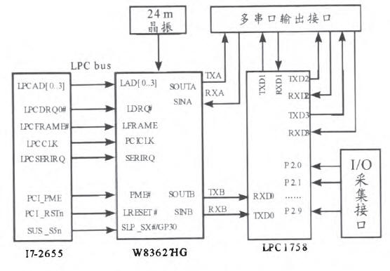
The block diagram of this interface design is shown in Figure 1. In the design, the Type2 COM-E mainboard of Germany Kontron Intel core i7-2655LE + QM67 PCH architecture is used as the core board, the carrier board is designed by itself, and four serial ports and multiple I/O ports are realized by W83627HG chip and LPCI758 ARM processor. Extensions.

Figure 1 Interface expansion design structure
According to the system design requirements, three extended serial ports are communication interfaces and data forwarding can be realized. The fourth extended serial port needs to be connected with the attitude meter. The attitude meter will send a frame of data every 10 ms. To ensure the real-time information, in the system design, the microprocessor LPCI758 calculates the serial port data and I/O port information. After the correction process, it communicates with the mainboard through another serial port.
2 Hardware Design
2.1 W83627
W83627 is a widely used super I/O chip of Taiwan WINBOND company. It adopts the Intel standard LPC bus and saves more chip resources than the ISA standard structure. It can expand 2 way high-speed serial port, support bi-directional printer port, and enhance. Parallel interface, PS/2 interface, MIDI interface, etc.
The W83627 uses the compatible PNP protocol to access the configuration registers for different types of configuration. It contains 11 logical devices and correspondingly represents 11 independent device functions: FDC logic device 0/PRT logic device 1, UART1 logic device 2, UART2 logic device 3, KBC logic device 5 and so on. Each logical device has its own configuration register, which can be accessed by the host by writing the corresponding logical device number to the logical device select register.
2.2 LPCI758
The LPC1758 is a Cortex-M3 microcontroller chip from NXP with a 3-stage pipeline and Harvard architecture. The maximum operating frequency is 100 MHz. Its peripheral components include 512kFlash, 64k of on-chip SRAM, Ethernet MAC, and USB2.0. 4 UARTs, 2 CAN channels, 8-channel 12-bit ADC, 10-bit DAC, and up to 70 general-purpose I/O ports.
LPC1758 ARM processor has 4 asynchronous serial ports that conform to 16C550 industry standard, built-in fractional divider, 16-byte FIFO, support DMA sending and receiving. Among them UARTl supports Modem and RS485/EIA485 mode, UART0, 2, 3 support IrDA interface.
The LPCI758 contains 5 sets of up to 70 GPIO pins, which are commonly used for input and output of digital signals such as LEDs, buzzer, and high and low status information. The support system is configured for pull-up/pull-down resistors, open-drain and relay modes.
2.3 Hardware Solution
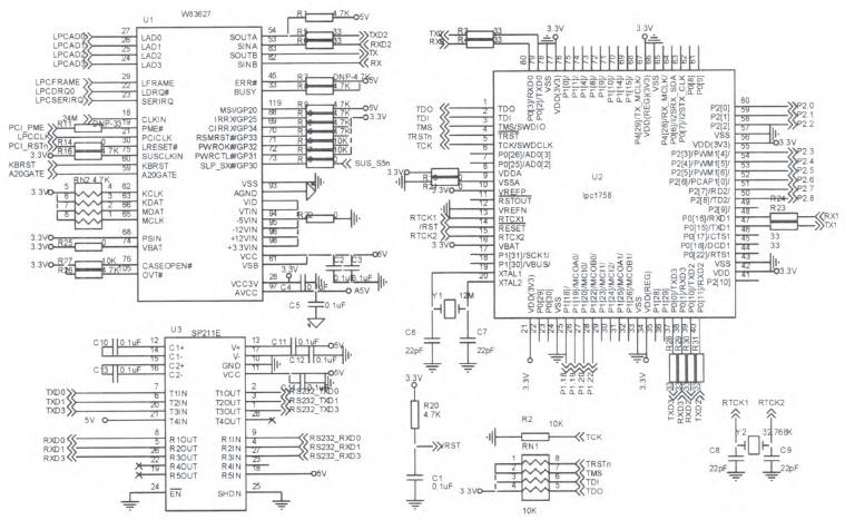
Interface expansion design circuit diagram shown in Figure 2, the COM-E motherboard first through the LPC bus and W83627HG chip connection, W83627 pin 22 to 29 for the LPC bus interface, with the motherboard B3 to B8 feet corresponding to connect; the first 19 feet for the PME power supply Management pins are connected to pin C15 of motherboard. Pin 21 is PCI clock input and connected to LPC bus clock B10. Pin 30 is reset signal. It should be noted that it cannot be connected to the system reset signal of main board. It should be connected to the motherboard PCI reset signal B50. . After external 24MHZ clock, W83627's 53/54 and 82/83 feet can realize LPC bus 2 UART serial port expansion.

Figure 2 interface expansion design circuit
The UARTB is used as the external data communication interface. The UARTA is connected to the 39140-pin UART2 of the LPCI758 chip to realize communication between the mainboard and the ARM chip, and the other three serial ports and multiple IO ports are extended by the ARM chip.
LPCI758 pin 1 to pin 5 is a JTAG interface and is used for program programming. Pins 19/20 and 13/15 are the internal clock and RTC pin, which are connected to a 12 MHz and 32.768 kHz passive crystal respectively. 80, 47/48, 37/8 are respectively set as UART0, UART1, UART3 3 expansion serial ports, and the extended serial port is connected with the level conversion chip SP211E to achieve RS232 serial communication with the peripherals. The P2[0] to P2[9] pins and P1[18] to P1[22] pins of the LPCI758 are general-purpose input/output ports. They are directly configured as GPIO pins and are connected to peripheral devices such as status switches/LEO/buzzers.
3 Software Design
3.1 System Workflow
The system design extends the four serial ports and multiple I/O interfaces through the LPCI758 processor. Among them UART0 is the input interface of the external attitude instrument information, UART2 is the communication interface of the main board. Nine I/O interfaces are connected to external status buttons/switches for quick control of digital inputs. The attitude instrument sends a complete data every 10 ms. The system software monitors the UART0 in real-time using the interrupt receiving method. After the new data is received, it is calculated and corrected by the ARM chip, and the correction result of the current status frame is updated every 10 ms. The current switching result is sent from UART2 to the COM-E main board. Two I/O interfaces are used for the LED indicator and the buzzer control level output. When the ARM chip receives a control command sent from the main board from UART2, it controls the I/O output level change and activates or deactivates the LED and buzzer. Device. The other three serial ports serve as an extended communication interface. When new data is received or sent, no processing is performed and communication with the mainboard is performed as it is.
3.2 Software Process
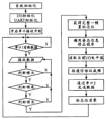
Serial port expansion software workflow diagram shown in Figure 3. First, the UART0 of the LPCI758 is in the receiving state. When the program receives the original information transmitted by the attitude meter, it enters the receive interrupt and automatically receives the data. At the same time, it judges whether the end is received according to the transmission protocol of the attitude instrument; after receiving the complete one frame signal, The program exits the receive interrupt, and calls the solver program to solve the information and store the result in the buffer. At the same time, the program reads the status information of the current GPIO port, and the GPIO information with the solution result information is in accordance with ARM and COME-E. The host's communication protocol is framed and sent from UART2 to the host.

Figure 3 Software Workflow
3.3 Programming
UART0 receives attitude information using interrupt receive mode:
Void UART0_IRQHandler(void)
While((LPC_UART0->IIR&0x01)==O)
{ switch (LPC_UART0->IIR&OxOE)
/*To determine if there is an interrupt pending*/
{ Case Ox04:/* Judgment Interrupt Flag */
GueRcvButO[GulNum0]=LPC_UART0->RBR;
/* Receive data interruption */
If (GueRcvBuf0[GulNum0]==0x32&&GucRevBuf0[GulNum0-1]==0x32&&GucRevBufO[GulNum0-2]==0xFF&&GucRcvBuf0[GulNum0-3]==0xFA&&GulNum0>=3) /* It is judged whether it is a frame header */
{ RecHead=1;
GucRcvButO[0]=0xFA;
GucRevBug)[1]=0xFF;
GucRevBuf0[2]=0x32;
GucRcvButO[3]=0x32;
GulNum0=3;
Else
{ if(ReeHead==1&&GulNum0==54)
/* Judge the frame length */
{flag0++;
RecHead=0;
GulNum0=0;
Break;}
}
GulNum0++;
If (GulNum0==128)
GulNum0=0;
Break;
Case OxOC; /* character timeout interrupt */
Break;
Default;
Break;}
}
}
Read the current level value of the specified GPIO port:
Void readGPIO(void)
{
PinIN=LPC_GPl02->FIOPIN0&0xlF; /*Read the value of P2.0-P2.4*/
PinOut=LPC_GPl01->FIOPIN2&OxOC; /*Read the value of P1.18-P1.19*/
P120=LPC_GPl01->FIOPIN2&0x10:/*Read the value of P1.20 output*/
P122=LPC_GPl01->FIOPIN2&Ox40:/*Read the value of P1.22*/
IODATA0=(PinIN<<2)|(PinOut>>2);/*IO Output value is lower 8 bits, 1byte */
IODATA1=(P120>>4)|(P122>>5);} /*IO output is 8 bits high, 1 byte */
Reading the corrected attitude data in the main function and framing the IO values ​​according to the protocol:
If(fiag0==1) // flag is 1, complete receiving a frame
SendBuff[0]=OxFF;
SendBuff[1]=OxEF;
SendBuff[29]=0xEF;
SendBuff[30]=OxFF; //Send frame header
Addr=(uint8_t *)(&f_roll);
Memcpy(SendBuff+2,addr,4);
//Read corrected roll angle value
Addr=(uint8_t *)(&f_pitch);
Memcpy(SendBuff+6,addr,4);
//Read the revised pitch angle
Addr=(uint8_t *)(&Dyaw);
Memcpy(SendBuff+10,addr,4);
//Read the corrected heading angle value
Rain=f_gyro[0];
Addr=(uint8_t *)(&mm);
Memcpy(SendBuff+14,addr,4);
//Read corrected X-direction speed
Mm=f_gyro[1];
Addr=(uint8_t *)(&mm);
Memcpy(SendBuff+18,addr,4);
//Read corrected Y direction speed
Mm=f_gyro[2];
Addr=(uint8_t *)(&mm);
Memcpy(SendBuff+22,addr,4);
//Read corrected Z direction speed
readGPIO();//Read the current GPIO value
SendBuff[26]=IODATA1;
SendBufff[27]=IODATA0;
uart2SendStr(SendBuff,31);//Serial2 send
Flag0=0;//flag bit is cleared
4 Conclusion
This design realizes the extended use of COM-E mainboards with multiple serial ports/IO ports and the preprocessing of serial port information under high real-time requirements. The design has been successfully applied to a military model project. After verification, the system has the advantages of simple design, small hardware size, and high reliability. At the same time, it can meet the high real-time requirements of attitude information, and has a wide range of embedded electronic device design. Application prospects.
600-800V Series Electric Compressor Three-phase Sealed Terminal
Shenzhen Capitol Micro-Electronics Co.,LTD , https://www.capitolgtms.com