I. Classification of voltage regulators According to different classification methods of voltage regulation, it can be divided into three types of electronic induction oil regulators, dry contact voltage regulators (direct voltage regulators and compensation regulators). Dry type non-contact voltage regulator (generally with voltage regulator with compensation) 2. Classification of voltage regulator: According to different classification of power supply environment, it can be divided into two types of single-phase AC voltage regulator three-phase communication Regulator III. Taking the dry contact voltage regulator as an example to analyze the working principle of the voltage regulator: Principle analysis of single-phase AC voltage regulator 1. Principle analysis of single-phase SVC direct voltage regulator
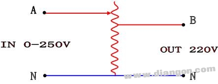
Figure II
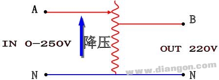 Figure II
 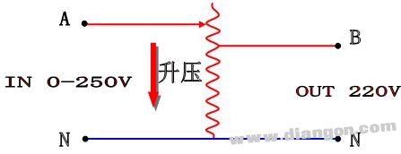 Figure 3 The capacity of such a regulator is entirely borne by the transformer's autotransformer. However, due to its manufacturing process, it cannot be made very large and can only be adapted to low-power applications. The power of the regulator is made even bigger, it is necessary to add a compensation transformer to realize the power expansion of the regulator. 2. Principle analysis of the single-phase compensation regulator (Figure 4)
 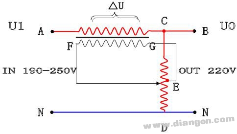 Figure 4 is a schematic diagram of a single-phase AC voltage regulator with compensation. It consists mainly of a voltage regulating transformer T1 and a compensation transformer T2. It can be seen from the figure that the low-voltage side coil of the compensation transformer is connected in series with the main circuit of the regulator. In the middle, then, the main energy of the output of the regulator is directly added to the output load through the low-voltage side coil of the compensation transformer. As long as the wire diameter of the secondary coil of the compensation transformer is made large enough, the power of the regulator is It can be made very large. The voltage regulator transformer T1 only needs to bear the difference between the input voltage and the output voltage, and the allowable input variation range of the regulator varies. The power of the voltage regulator T1 is often the actual capacity of the regulator. A fraction of this, which is determined by the ratio of the regulator to determine the size of the transformer. Below we analyze its working principle: The regulator is mainly used to provide the compensation voltage, the magnitude and direction of this compensation voltage The movement of the sliding arm of the pressure transformer can be changed, which can obtain the compensation voltage that can be changed in size and direction on the low voltage side of the compensation transformer. This voltage will be input to the input terminal. The supplied voltage is vector superimposed. The output voltage is stabilized at the required set point. An example is given to illustrate: The input voltage U1=240V, the output voltage is required to be stable at UO=220V. Then there is the following equation: UO= U1-△U is also the direction of △U is opposite to the direction of U1, the size is just 20V. The input voltage U1=200V, the output voltage is required to be stable at UO=220V. Then there is the following equation: UO=U1+△U That is, the direction of ΔU should be the same as the direction of U1, and the size is just 20V. It can be seen from the above formula that the compensation voltage ΔU is transmitted from the high voltage side of the compensation transformer to the compensation transformer through the iron core. The low voltage side is then superimposed with the input voltage vector. The compensation transformer is mainly responsible for compensating the voltage transmission, while the voltage regulating transformer is responsible for providing the compensation voltage whose direction and size can be changed. Below we analyze how the voltage regulating transformer changes the compensation voltage. Direction and size: As can be seen from Figure 5, the CD point of the voltage regulating transformer is connected across the 220V voltage. The E point is just the center point of the voltage regulating transformer. We assume that the sliding arm stops at point C.
 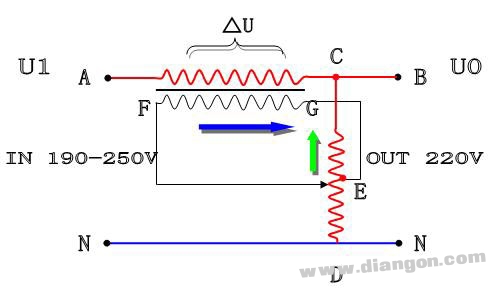 Figure 5 When the sliding arm stops at point D, (Figure 6), the voltage applied to the high voltage side of the compensation transformer is G point higher than point F, and the current flows from point G to point F. In this way, compensation is added to the compensation transformer. The voltage changes direction.
 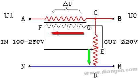 Figure 6. How to change the compensation voltage of the voltage regulating transformer, of course, is also realized by the movement of the sliding arm. When the sliding arm is away from the center point E of the regulating transformer, the F point and the G point of the high voltage side of the compensation transformer are obtained. The higher the voltage, the lower the voltage. When the input voltage of the regulator is just 220V, when the slider moves to point E, the compensation voltage between point F and point G is 0. The low side of the compensation transformer is Does not add or subtract. The output voltage is the input voltage. IV. Three-phase voltage regulator working principle: The three-phase voltage regulator is actually connecting the three voltage regulator units with the "Y" connection method. The control circuit board and the motor drive system are used to control the voltage regulating transformer to achieve the function of stabilizing the output voltage. If the sliding arms of the three voltage regulating transformers are driven by one motor, the voltage regulating mode is the regulating voltage regulator. The voltage regulators of the voltage regulating transformer are independently adjusted by three motors. The three-phase voltage regulator is the same. The working principle is the same as that of the single-phase voltage regulator. 5. How to ensure the continuous output of the voltage regulator During the voltage regulation process, the regulator is changed by moving the carbon brush. The number of coil turns is achieved. Then, the adjustment requires that the coil be in contact with the coil. Otherwise, there will be a power failure. How does the regulator maintain a continuous output? 1. The carbon brush must have a certain thickness. When the carbon brush has not completely removed the coil that has been touched, the carbon brush has already touched another coil of the coil.
 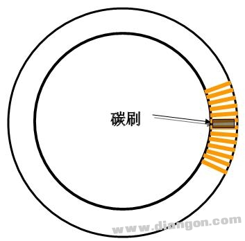 Figure 7 3. Two åŒ (at least two è·¨) must be connected during the movement. 4. There is always a turn-to-turn short circuit in the operation of the regulator. The thicker the thickness of the carbon brush, the more the number of turns of the short circuit. Therefore, the voltage regulator The thickness of the carbon brush varies according to the diameter of the regulator. 5. Because the short circuit between turns is harmful, it will cause a short circuit, so it is necessary to control its size, so the voltage of the regulator is generally Below 1V, common high-power voltage regulators have a voltage of 0.8-0.9V, and small powers are smaller, generally ranging from 0.4-0.7V. If the voltage is too high, the stability of the regulator is worse. Easy to burn.
 Silent Type Diesel Generator,Soundproof Diesel Generator,Diesel Generator Set,Pump Generator
Jiangsu Vantek Power Machinery Co., Ltd , https://www.vantekpower.com