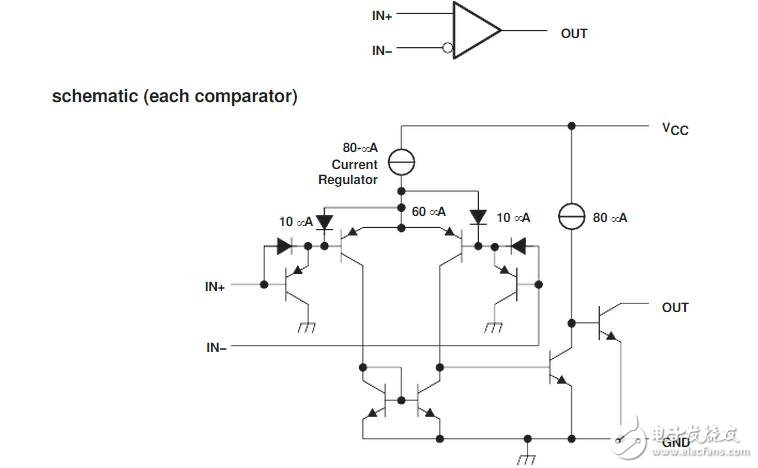
The comparator is usually composed of an integrated operational amplifier. Unlike the ordinary operational amplifier circuit , the integrated amplification in the comparator is mostly in an open loop or positive feedback state . As long as a small signal is applied to both inputs, the op amp enters the non-linear region and is part of the nonlinear application range of the integrated op amp. When analyzing the comparator, the principle of “ virtual break †is still established, and the concepts of “ virtual short †and “ virtual ground †are only adapted when judging the critical situation.
First, zero level comparator (zero-crossing comparator)
The voltage comparator is a circuit that compares and identifies an analog input signal ui with a fixed reference voltage UR.
A comparator with a reference voltage of zero is called a zero-level comparator. According to the different input modes, it can be divided into two kinds of zero potential comparators, inverting input and non-inverting input, as shown in Figure 1(a) and (b).
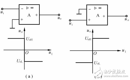
Figure 1 Zero-crossing comparator
(a) inverting input; (b) in-phase input
Threshold voltage and transmission characteristics are commonly used to describe the operational characteristics of the comparator.
The threshold voltage (also referred to as the threshold level) is the input voltage value when the comparator output voltage is tripped, which is simply referred to as the threshold value, and is represented by the symbol UTH.
The transmission characteristic is the relationship between the output voltage uo of the comparator and the input voltage ui at the plane rectangular coordinates.
The general procedure for drawing the transmission characteristics is to first find the threshold and then analyze the input voltage from the lowest to the highest (forward process) and the input voltage from highest to lowest (negative process) according to the specific circuit of the voltage comparator. Next, the output voltage changes regularly, and then draws the transmission characteristics.
Second, any level comparator (capture zero comparator)
The ground terminal in the zero-level comparator is connected to a reference voltage UR (set to DC voltage). Since the size and polarity of the UR can be adjusted, the circuit becomes an arbitrary level comparator or a zero-trap comparator.
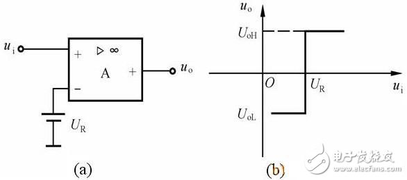
Figure 2 arbitrary level comparator and transmission characteristics
(a) arbitrary level comparator; (b) transmission characteristics
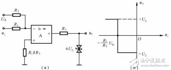
Figure 3 Level detection comparator signal transmission characteristics
(a) level detection comparator; (b) transmission characteristics
The level voltage comparator has a simple structure and high sensitivity, but its anti-interference ability is poor. That is to say, if the input signal changes due to interference near the threshold, the output voltage will repeatedly jump between the high and low levels, which may cause the output state to malfunction . In order to improve the anti-interference ability of the voltage comparator, a hysteresis voltage comparator with two different thresholds is described below.
Third, hysteresis voltage comparator
Hysteresis comparators are also known as Schmitt triggers , hysteresis comparators. A characteristic of such a comparator is that when the input signal ui gradually increases or decreases, it has two thresholds and is unequal, and its transmission characteristic has a shape of a "hysteresis" curve.
The hysteresis comparator also has two methods: inverting input and non-inverting input.
UR is a fixed voltage, and changing the UR value can change the threshold and the magnitude of the hysteresis.
Taking the inverted hysteresis comparator shown in Figure 4(a) as an example, calculate the threshold and plot the transmission characteristics.
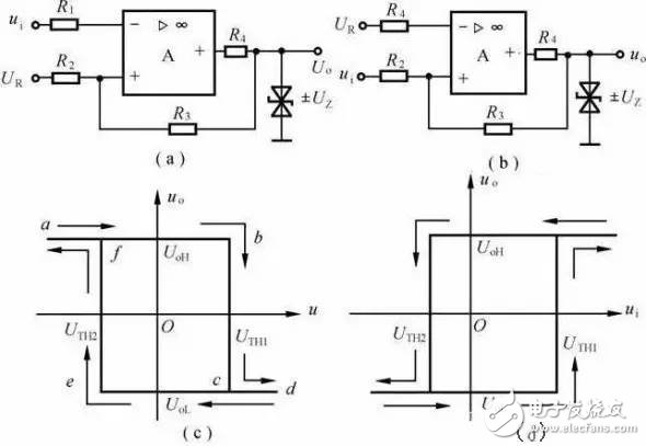
Figure 4 hysteresis comparator and its transmission characteristics
(a) inverting input; (b) in-phase input
1. The threshold of the forward process

Abcd segment forming a voltage transfer characteristic
2. The threshold of the negative process

Forming a defa segment on the voltage transfer characteristic . Since it is similar in shape to the hysteresis loop, it is called a hysteresis voltage comparator.
It is not difficult to calculate the two thresholds of the in-phase hysteresis comparator shown in Fig. 4(b) by using the threshold condition and the superposition principle method.
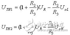
The difference between the two thresholds ΔUTH=UTH1–UTH2 is called the hysteresis.
From the above analysis, it can be seen that changing the R2 value can change the magnitude of the backlash , and adjusting the UR can change UTH1 and UTH2 , but does not affect the magnitude of the backlash . That is, the transmission characteristics of the hysteresis comparator will be shifted to the right or left, and the hysteresis curve width will not change.
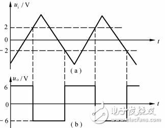
Figure 5 Waveform transformation of the comparator
(a) input waveform; (b) output waveform
For example, the transmission characteristics of the hysteresis comparator and the waveform of the input voltage are as shown in Figs. 6(a) and (b). According to the transmission characteristics and two thresholds (UTH1=2V, UTH2=–2V), the waveform of the output voltage uo can be drawn, as shown in Fig. 6(c). It can be seen from Figure (c) that ui changes between UTH1 and UTH2 and does not cause uo jumps. However, the hysteresis also causes the hysteresis of the output voltage, causing the level discrimination to produce an error.
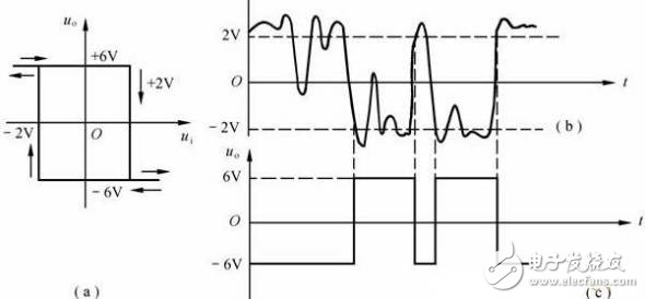
Figure 6 shows the strong anti-interference ability of the hysteresis comparator
(a) known transmission characteristics; (b) known ui waveforms;
(c) uo waveform drawn according to transmission characteristics and ui waveform
Fourth, the window voltage comparator
The level comparator and the hysteresis comparator have one characteristic in common, that is , when ui changes in one direction (forward process or negative process), uo only jumps once . Only the level of one input signal can be detected. This comparator is called a single-limit comparator.
The double limit comparator is also called the window comparator. It is characterized by a single direction change of the input signal (for example, ui is raised from a low enough monotonic to a high enough) to make the output voltage uo jump twice, and its transmission characteristics are as shown in Fig. 7(b), which is shaped like a window. For the window comparator. The window comparator provides two thresholds and two output steady states that can be used to determine if ui is between some two levels. Â Â Â Â
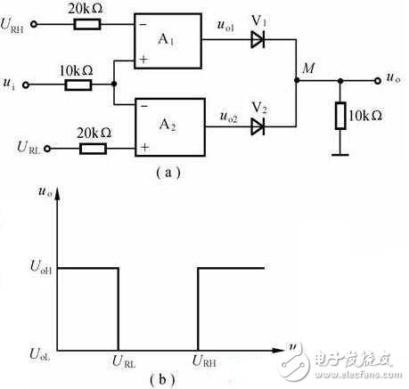
Figure 7 window comparator circuit and transmission characteristics
(a) window comparator; (b) transmission characteristics
Toolkits For Cutting Mahine and Cutting Materials
It is suitable for the blade of the Screen Protector Cutting Machine and the tools for installing the Screen Protection Film.
If you want to learn more about Accesseries For Cutter,Screen Protector Cleaning Tool, Cutting Blade, Cell Phone Scraper Tool, Tool Kit, Cutting Head Parts please click "Product Details" to view Accesseries For Cutter,Screen Protector Cleaning Tool, Cutting Blade, Cell Phone Scraper Tool, Tool Kit, Cutting Head Parts parameters, models, pictures, prices and other information .
Whether you are a group or an individual, we will try our best to provide you with accurate and comprehensive information about Accesseries For Cutter,Screen Protector Cleaning Tool, Cutting Blade, Cell Phone Scraper Tool, Tool Kit, Cutting Head Parts!Accesseries For Cutter,Screen Protector Cleaning Tool, Cutting Blade, Cell Phone Scraper Tool, Tool Kit, Cutting Head Parts
Shenzhen Jianjiantong Technology Co., Ltd. , https://www.jjthydrogelprotector.com