introduction
The voltage outputted by the rectifier circuit is a one-way pulsating voltage and cannot be directly used by electronic circuits. Therefore, the output voltage should be filtered to eliminate the AC component in the voltage and become DC power for use in the electronic circuit. In the filter circuit, devices that have special impedance characteristics to alternating current, such as capacitors and inductors, are mainly used. This paper analyzes its various forms of filter circuits.
First, the type of filter circuit
The filter circuit mainly has the following types: capacitance filter circuit, which is the most basic filter circuit; π-type RC filter circuit; π-type LC filter circuit; electronic filter circuit.
Second, the principle of filtering
1. Characteristics of one-way pulsating DC voltage
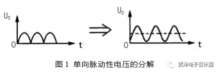
As shown in Figure 1 (a). It is a unidirectional pulsating DC voltage waveform. It can be seen from the figure that the directionality of the voltage is consistent at all times, but it is fluctuating in voltage amplitude, that is, on the time axis, the voltage exhibits periodicity. Change, so it is pulsating.
However, according to the waveform decomposition principle, this voltage can decompose a DC voltage and a set of AC voltages with different frequencies, as shown in Figure 1(b). In Fig. 1(b), the dotted line portion is a unidirectional pulsating DC voltage U. The DC component in the solid line is the AC component in the UO.
2. Capacitor filtering principle
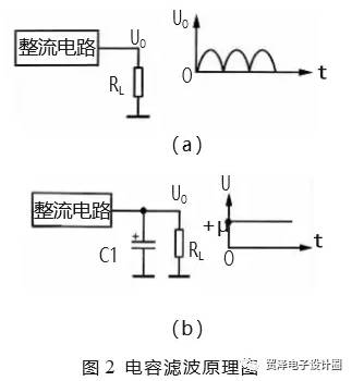
According to the above analysis, the unidirectional pulsating DC voltage can be decomposed into two parts, AC and DC. In the filter circuit of the power supply circuit, the AC component of the voltage can be filtered out by utilizing the characteristics of the "straight through" of the capacitor and the energy storage characteristics, or by utilizing the characteristic of the "straight traffic" of the inductor. Figure 2 shows the schematic of the capacitive filter.
Figure 2 (a) shows the output circuit of the rectifier circuit. After the AC voltage is passed through the rectifier circuit, the output is a unidirectional pulsating direct current, that is, UO in the circuit.
Figure 2(b) shows the capacitor filter circuit. Since the capacitor C1 is equivalent to an open circuit to the direct current, the DC voltage output from the rectifier circuit cannot pass through C1 to ground, and is only added to the load RL as RL. For the AC component of the rectifier circuit output, because C1 has a large capacity and a small capacitive reactance, the AC component flows to the ground through C1 and cannot be added to the load RL. Thus, the required DC voltage +U is taken out from the unidirectional pulsating direct current by the filtering of the capacitor C1.
The larger the capacity of the filter capacitor C1, the smaller the capacitive reactance to the AC component, and the smaller the AC component remaining on the load RL, the better the filtering effect.
3. Inductive filtering principle
Figure 3 shows the schematic of the inductive filtering. Since the inductor L1 is equivalent to the path of the direct current, the direct current voltage output from the rectifier circuit is directly applied to the load RL.
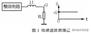
For the AC component of the rectifier circuit output, because of the large inductance of L1, the inductance is large, which greatly hinders the AC component and prevents the AC from flowing through C1 to the load RL. Thus, the required DC voltage +U is taken out from the unidirectional pulsating direct current by the filtering of the inductor L1.
The larger the inductance of the filter inductor L1 is, the larger the inductive reactance to the AC component is, and the smaller the AC component remaining on the load RL is, the better the filtering effect is, but the DC resistance is also increased.
Third, π-type RC filter circuit identification method
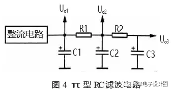
Figure 4 shows the π-type RC filter circuit. C1, C2 and C3 in the circuit are 3 filter capacitors, R1 and R2 are filter resistors, C1, R1 and C2 form the first π-type RC filter circuit, and C2, R2 and C3 form the second π-type RC filter. Circuit. Since this filter circuit is in the form of a Greek letter π and a resistor or a capacitor, it is called a π-type RC filter circuit.
The principle of the π-type RC filter circuit is as follows:
(1) The filtering principle of this circuit is that the voltage output from the rectifier circuit is first filtered by C1, and most of the AC components are filtered out, and then added to the filter circuit composed of R1 and C2. The capacitive reactance of C2 and R1 constitute a voltage dividing circuit. Because the capacitive reactance of C2 is small, the partial voltage attenuation of the AC component is large, achieving the filtering purpose. For DC power, since C2 has a DC blocking function, the R1 and C2 voltage dividing circuits do not have a voltage division attenuation for DC, so that the DC voltage is output through R1.
(2) When the size of R1 is constant, increasing the capacity of C2 can improve the filtering effect. When the capacity of C2 is constant, increasing the resistance of R1 can improve the filtering effect. However, the resistance of the filter resistor R1 should not be too large, because the DC current flowing through the load flows through R1, and a DC voltage drop occurs at R1, which reduces the DC output voltage Uo2. The greater the resistance of R1, or the greater the current flowing through the load, the greater the voltage drop across R1, making the DC output voltage lower.
(3) C1 is the first section of filter capacitor. Increase the capacity to improve the filtering effect. However, when C1 is too large, the charging time of C1 is very long when the power is turned on. This charging current flows through the rectifier diode. When the charging current is too large and the time is too long, the rectifier diode is damaged. Therefore, the use of this π-type RC filter circuit can make the C1 capacity smaller, and further improve the filtering effect by rationally designing the values ​​of R1 and C2.
(4) There are three DC voltage output terminals in this filter circuit, which output three sets of DC voltages Uo1, Uo2 and Uo3. Among them, Uo1 is only filtered by capacitor C1; Uo2 is filtered by C1, R1 and C2 circuits, so the filtering effect is better, the AC component in Uo2 is smaller; Uo3 is filtered by 2 filter circuits, the filtering effect is the most Ok, so the communication component in Uo3 is the least.
(5) The magnitude of the three DC output voltages is different. Uo1 has the highest voltage. Generally, this voltage is directly applied to the power amplifier circuit or added to the circuit that requires the highest DC operating voltage and the largest operating current. The Uo2 voltage is slightly lower because the resistor R1 has a voltage drop to the DC voltage. Uo3 voltage At the lowest, this voltage is generally supplied to the front-end circuit as a DC operating voltage because the DC operating voltage of the pre-stage circuit is relatively low and the AC component in the DC operating voltage is required to be small.
Fourth, π-type LC filter circuit identification method
Figure 5 shows the π-type LC filter circuit. The π-type LC filter circuit is basically the same as the π-type RC filter circuit. This circuit only replaces the filter resistor with the filter inductor, because the filter resistor has the same resistance to DC and AC, and the filter inductor has large resistance to AC inductor and small resistance to DC, which can improve the filtering effect without reducing it. DC output voltage.
In the circuit of Figure 5, the unidirectional pulsating DC voltage output by the rectifier circuit is first filtered by capacitor C1 to remove most of the AC component and then added to the L1 and C2 filter circuits.
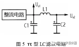
For the AC component, L1 is very resistant to it, so that the AC voltage drop on L1 is large and the AC component added to the load is small.
For DC power, since L1 does not exhibit inductive reactance, it is equivalent to a path. At the same time, the filter inductor uses a relatively large wire diameter and a small DC resistance. Therefore, there is substantially no voltage drop to the DC voltage, so the DC output voltage is relatively high. The main advantage of using an inductive filter.
Five, electronic filter identification method
Electronic filter
Figure 6 shows the electronic filter. VT1 in the circuit is a triode, which acts as a filter tube. C1 is the base filter capacitor of VT1, R1 is the base bias resistor of VT1, RL is the load of this filter circuit, and C2 is the filter capacitor of the output voltage.
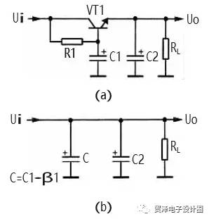
The working principle of the electronic filter circuit is as follows:
1 VT1, R1, C1 form an electronic filter circuit, this circuit is equivalent to a capacitor with a capacity of C1 × β1, β1 is the current amplification factor of VT1, and the current amplification factor of the transistor is relatively large, so the equivalent The capacitance is large, and the filtering performance of the visible electronic filter is very good. The equivalent circuit is shown in Figure 6(b). In the figure, C is the equivalent capacitance.
The R1 and C1 in the 2 circuit form an RC filter circuit. R1 provides the base bias current for VT1 and is also the filter resistor. Since the current flowing through R1 is the base bias current of VT1, this current is very small, and the resistance of R1 can be made relatively large, so that the filtering effect of R1 and C1 is good, so that the VT1 base is in the DC voltage. There are few communication components. Since the emitter voltage has the characteristics of following the base voltage, the AC component of the VT1 emitter output voltage is also small, achieving the purpose of filtering.
3 In the electronic filter, the filtering is mainly realized by R1 and C1, which is also the RC filter circuit, but it is different from the RC filter circuit described earlier. The DC current flowing through the load in this circuit is the emitter current of VT1, and the current of the filter filter resistor R1 is the base current of VT1, and the base current is small, so the resistance of the filter resistor R1 can be set large ( The filtering effect is good, but it does not cause the DC output voltage to drop a lot.
The resistance value of R1 in the circuit determines the base current of VT1, which determines the tube voltage drop between the collector and emitter of VT1, which determines the DC voltage of the VT1 emitter output, so change R1. Size, you can adjust the size of the DC output voltage +V.
2. Electronically regulated filter
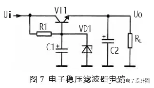
Figure 7 shows another electronically regulated filter with a Zener diode VD1 connected between the base and ground of VT1 compared to the previous circuit. The principle of electronic voltage regulation is as follows:
After the Zener diode VD1 is connected between the base and ground of VT1, the input voltage is reverse biased by the voltage regulator diode VD1 via R1. At this time, the voltage regulation characteristic of VD1 stabilizes the base voltage of the VT1 tube. The DC voltage of the VT1 emitter output is also relatively stable. Note: The stability of this voltage is determined by the regulation characteristics of VD1 and has nothing to do with the electronic filter circuit itself.
R1 is also the current-limiting protection resistor of VD1. After adding the Zener diode VD1, changing the size of R1 does not change the output voltage of the VT1 emitter. Since the PN1 has a PN junction voltage drop at the emitter junction, the emitter output voltage is slightly smaller than the regulated value of VD1.
C1, R1 and VT1 also form an electronic filter circuit for filtering.
In some cases, in order to further improve the filtering effect, a double-tube electronic filter circuit can be used, and two electronic filter tubes constitute a composite tube circuit. Thus, the total current amplification factor is the product of the current amplification factor of each tube, which obviously improves the filtering effect.
Sixth, the power supply filter circuit map summary
The main points of attention regarding the analysis of the power supply filter circuit are as follows:
(1) When analyzing the working principle of the filter capacitor, it mainly uses the "straight-through" characteristic of the capacitor, or the charging and discharging characteristics, that is, when the rectifier circuit outputs a unidirectional pulsating DC voltage, the filter capacitor is charged when there is no one-way pulsation. When the DC voltage is output, the filter capacitor discharges the load.
(2) When analyzing the working principle of the filter inductor, it is mainly recognized that the resistance of the inductor to the direct current is small, no inductive reactance, and there is an inductive reactance to the alternating current.
(3) When performing electronic filter circuit analysis, it is necessary to know that the capacitance on the base of the electronic filter tube is a key component of the filter. In addition, to analyze the DC circuit, the electronic filter tube has a base current and a collector and emitter current. The current flowing through the load is the emitter current of the electronic filter tube. The base current can be adjusted to adjust the collector of the electronic filter tube. The tube voltage drop between the emitter and the emitter, thereby changing the magnitude of the DC voltage output by the electronic filter.
(4) The electronic filter itself has no voltage regulation function, but the DC voltage of the output can be stabilized after the Zener diode is added.
SMC Board To Board Connector Section.
Compact high density design
Design of super reliable double beam contact
High speed signal transmission rate up to 3 Gbit / S
Polarization to ensure accurate connection
Locating pin for PCB placement
Welded bracket for secure PCB
Wide operating temperature range
Height range of non matching stack
For full automation board components
SMC Board To Board Connector Section
ShenZhen Antenk Electronics Co,Ltd , https://www.atkconnectors.com