1. Working principle of variable frequency speed regulation and constant pressure water supply system
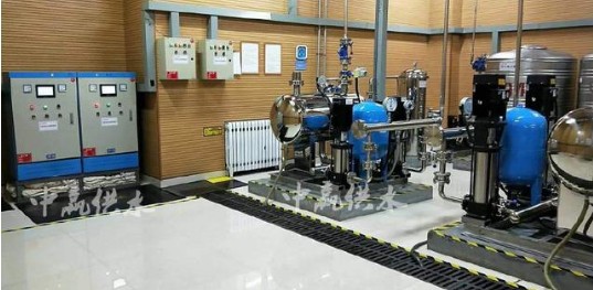
Compared with the water supply by the high-level water tank on the water tower or the roof of the building, the variable frequency speed and constant pressure water supply has the advantages of low investment, energy saving, and less chance of secondary pollution of water quality. More and more cities and residential communities have or are planning to adopt it. Variable frequency speed regulation and constant pressure water supply. The structure of variable frequency speed regulation and constant pressure water supply system is shown in Figure 1.
The working principle of the variable frequency speed regulation and constant pressure water supply system is: the controller detects the actual water pressure value, compares the difference between the set water pressure value and the actual water pressure value, and then outputs the control signal to the inverter after calculating according to the PID control law. Then adjust the power supply voltage and frequency of the water pump motor according to the input signal of the controller.
When the water consumption increases, the controller controls the frequency converter to increase the voltage and frequency of the motor, the speed of the water pump increases, and the water output increases; when the water consumption decreases, the controller controls the frequency converter to reduce the voltage and frequency of the motor and the speed of the water pump. Decrease, the water output decreases. Through this control method, the pressure of the water pipe can be maintained at the set value.
Due to the high price of the frequency converter, the frequency conversion speed regulation and constant pressure water supply system usually adopts multiple pumps to operate in parallel, and several water pumps share one frequency converter. When working, the controller controls the power distribution system to automatically select the number of pumps that need to be put into operation according to the water consumption. The general method is to keep one of the pumps under the control of the inverter, and the other pumps are in operation according to the changes in the water supply. Run at full speed under frequency or stop on standby.


2. Design of single-chip microcomputer controller for variable frequency speed regulation and constant pressure water supply system
2.1 Hardware design
The principle wiring diagram of the single-chip microcomputer controller and the variable frequency speed regulation constant pressure water supply system is shown in Figure 2. The system uses Atmel’s AT89C51 microcontroller as the control CPU (because the microcontroller has a 4KB Flash Memory on-chip); in order to ensure the stable and reliable operation of the system, MAX813 is used as the system’s voltage monitoring and Watchdog circuit; the pressure transmitter sends 4~ The 20mA pressure signal is converted into a 0~5V voltage signal by IC7; the A/D conversion circuit ADC0809 converts the detected water pressure value of the pressure sensor and the set value of the set potentiometer into digital quantities for use by the single-chip microcomputer; D/ The A conversion circuit uses DAC0832 to convert the control input of the single-chip microcomputer into a 4-20mA current loop to control the output frequency of the inverter. The control signals from the single-chip microcomputer to the power distribution part and some control switch commands of the system are isolated by the photoelectric coupling circuit to reduce the influence of the strong current loop on the single-chip microcomputer.
2.2 Software design
Suppose there are two water pumps in the water supply system, of which pump 1 is operated at variable frequency and pump 2 is operated at power frequency. The contactors are started or stopped respectively, and the single-chip microcomputer controls the operation of the contactors through relays. The software design is as follows:
2.2.1 Microcontroller interface address allocation and control port function
A/D converter ADC0809: 80XXH~87XXH; The pressure sensor is the IN0 channel, and the potentiometer is set to the IN1 channel.
D/A converter DAC0832: 08XXH.
Water pump 1 relay controls P1.0: when P1.0=0, water pump 1 is turned on; when P1.0=1, water pump 1 is stopped.
Water pump 2 relay controls P1.1: when P1.1=0, water pump 2 is turned on; when P1.1=1, water pump 2 is stopped.
Power-on command P1.2: When P1.2=0, the system starts to work, when P1.2=1, the system stops working.
2.2.2 Software programming
The single-chip microcomputer controller software of the variable frequency speed regulation and constant pressure water supply system includes the main program, the control quantity calculation subprogram, the relay control subprogram, the A/D conversion subprogram, and the delay subprogram. The relay control subroutine completes the operation and stop control of the water pump 2. Since the control quantity of the frequency converter is directly related to the running speed of the water pump 1, the program can judge the working status of the water pump 1 according to the control quantity of the frequency converter. If the control quantity is zero, it means that the system pressure is too high and the water pump 1 has been adjusted to the lowest speed, and then pump 2 needs to stop working; if the control quantity is the maximum, it means that the system pressure is too low and the water pump 1 has been adjusted to the highest speed. Requires water pump 2 to be put into operation. Due to the large inertia of the pressure change of the water supply system, when the maximum or minimum value of the control quantity appears, it needs to be delayed for a period of time. After repeated measurement during the delay stage, if the control quantity remains unchanged, switch again. When the system has more than 2 pumps, the switching principle is the same, but a cycle judgment program for judging the on and off states of multiple pumps needs to be added.
The control quantity calculation subroutine includes the calculation of the inverter control quantity and the output of the control quantity, and the control law adopts the PID regulation law.
The block diagram of the control quantity calculation subroutine is shown in Figure 6.
3. Conclusion
The frequency conversion speed regulation and constant pressure water supply system is the development direction of water supply in modern cities and living quarters. The frequency conversion water supply system controlled by single-chip microcomputer has the characteristics of reliable work, easy implementation and low price, and is an ideal controller.
frp rod,frp rod manufacturing,optical fiber cable,Solid Round Durable FRP Rod
Taizhou Yunzhi Power Equipment Co., Ltd. , https://www.thim-insulator.com