Smart antenna system without adaptive algorithm
This paper proposes a smart antenna based on the equilateral side-lobe needle beam pattern. In order to compare with the smart antenna using adaptive algorithm, this paper separately simulates the capacity expansion of these two different smart antennas when used in CDMA system. The results show that in the CDMA system, without using an adaptive algorithm, only the equal side lobe needle beam smart antenna can be used, and the expansion performance similar to the adaptive smart antenna can be achieved. The advantages of the equal side lobe needle beam smart antenna are: No iteration, fast response and good robustness.
Keywords: smart antenna; circular array; CDMA system
Smart Antenna without Employing AdapTIve Algorithm
FENG Zheng-he, ZHANG Zhi-jun
(Department of Electronics Engineering, Tsinghua University, Beijing 10084, China)
Abstract: A smart antenna based on equal side-lobe pencil patterns was proposed in this paper.For comparing with smart antennas which employ adapTIve algorithm, the capacity enhancement of both smart antennas in CDMA system is evaluated.The simulaTIon result shows that the adapTIve algorithm does not have to be employed. Smart antennas with equal side-lobe pencil patterns has almost the same capacity enhancement performance. Merits of equal side-lobe pencil pattern smart antennas are without iteration, faster response and better robustness.
Key words: smart antenna; circular array; CDMA
1. Introduction With the rapid popularization of mobile communications in China, the limited communication band has become increasingly crowded. In order to improve the utilization of the communication band, people have adopted a variety of channel multiplexing methods: frequency division multiple access (FDMA), time division multiple Address (TDMA), code division multiple access (CDMA), etc. But their ability to expand capacity is not unlimited. Smart antennas [1 ~ 6] study the problem of communication expansion from a new perspective, it uses space diversity for expansion, It can be combined with traditional multiplexing technology to maximize the use of limited frequency band resources. It can also effectively solve interference problems, expand the coverage area of ​​base stations, and reduce radiated power.
Smart antennas can be divided into two categories based on the principle of capacity expansion:
1. Expansion of soft capacity [1 ~ 3]. Such as CDMA system, in this type of system, because the number of available channels is sufficient, the capacity of the system depends on the signal-to-noise ratio of the system. Smart antenna can improve the signal-to-noise ratio of the system, For a given signal-to-noise ratio threshold, the system using smart antennas can accommodate more users and achieve the purpose of capacity expansion.
2. Expansion of hard capacity [4 ~ 6]. Such as FDMA, TDMA and other systems, in this type of system, smart antennas use their spatial diversity capabilities to enable multiple users with different spatial angles to use the same traditional channel (frequency division channel, frequency division channel, Time-division channel). Hard capacity expansion actually divides a traditional channel into several space-division channels, thereby increasing the system capacity exponentially.
Smart antennas are classified in the form of implementation, and can also be divided into two categories:
1. The adaptive algorithm forms a directional graph. The adaptive algorithm usually takes the maximum signal-to-noise ratio of the output signal as the objective function, and uses an iterative algorithm to make the system's signal-to-noise ratio the best.
2. Isolateral lobe needle beam pattern. It determines the direction of arrival (DOA) of the user signal through direction finding, and then points the main lobe of the isolateral lobe pattern to the user's direction, thereby improving the user's signal-to-noise ratio. The DOA detection is a relatively mature technology. There are many algorithms such as MUSIC [7], ESPRIT [8], and the experimental results of the 900MHz mobile communication band have also been reported [9].
The smart antennas can be classified according to the principle of expansion and the form of implementation to obtain Table 1. Existing work has studied adaptive soft expansion, adaptive hard expansion, and needle beam pattern hard expansion. This article will compare adaptive soft expansion Expansion of smart antennas, research on needle beam soft expansion smart antennas.
Table 1
| Adaptive pattern | Needle beam pattern | |
| Soft capacity expansion | [1 ~ 3] | This article |
| Hard capacity expansion | [5 ~ 6] | [4] |
| Second, the adaptive smart antenna and needle beam smart antenna Figure 1 is a block diagram of the smart antenna beam control system. The smart antenna is an array antenna. All smart antenna systems change the weight of each array element signal in the array antenna and then It is superimposed to complete the spatial processing of the signal. For a smart antenna system with N units, processing each user requires N equivalent weighters, and if there are M users in total, N * M equivalents are required Weighter. In an actual system, the work of multiple equivalent weighters can be completed by a high-performance processing chip, which greatly reduces the complexity of the system. The system shown in Figure 1 can complete the processing of a user signal. Different implementation forms of smart antennas mainly reflect the implementation form of the beam control module in the block diagram of FIG. 1, which will be discussed separately below. |
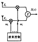
Figure 1 Schematic diagram of smart antenna beam control Adaptive smart antenna system, iteratively obtains a set of weighted vectors, so that the ratio of the required signal in the array output signal S (t) to all other user signals is maximized, that is, the signal-to-interference ratio is maximum. With this implementation, the system It has the highest signal-to-interference ratio. However, due to the iterative method, the response speed of the system is limited. For high-speed mobile users, the performance of the system will also be affected.
When the weighted signal is known, the array antenna pattern can be calculated from equation (1). Where g (θ) is the array pattern; ωm is the weighted value of the m-th signal; φm (θ) is the signal reaching the array from a spatial angle Phase difference at unit m.
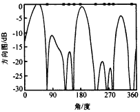
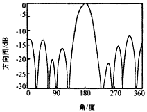
Figure 2 Adaptive direction diagram Figure 3 is an isolateral lobe needle beam pattern. The isolateral lobe needle beam pattern can also be calculated by formula (1). The difference between the isolateral lobe pattern and the adaptive pattern is that the way in which the weighted signal is generated is different, etc. The weighting values ​​of the side lobe pattern are pre-calculated. When the side lobe smart antenna system is working, the signal arrival angle (DOA) needs to be determined by the direction finding algorithm first, and then the main lobe of the pattern is selected by selecting the appropriate weight. Point to the user's direction of arrival. This type of smart antenna is used to ensure the suppression of the interference in the non-main lobe area by the low equal side lobe level. For the interference in the main lobe area, the equal side lobe needle smart antenna system is used It cannot be suppressed. Since the width of the main lobe of the system pattern is determined by the aperture of the antenna array, the adaptive smart antenna's ability to suppress interference signals in the main lobe is also very limited. Compared with the adaptive smart antenna, the side-lobe intelligence The antenna does not need iteration, the response speed is fast, and the robustness of this scheme is better. |
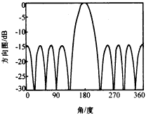
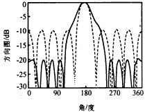
Figure 3 -15dB isolateral lobe needle beam pattern 3. Smart antenna system comparison simulation results This section gives the adaptive directional pattern (Applebaum algorithm [11]), -10dB equal side lobe needle beam pattern (as shown in Figure 4 dotted line), -15dB equal side lobe needle Simulation results of the performance of four smart antenna systems based on the shape of the beam pattern (Figure 3) and the -20dB equal side lobe needle beam pattern (Figure 4 solid line). The system used in the simulation uses the spacing of adjacent array elements at half wavelength The 8-element circular array assumes that the array uses isotropic elements. The iteration process is not considered for the adaptive smart antenna during simulation, which is the final steady-state result of the system.
Figure 4 -10dB, -20dB and other side lobe needle beam pattern The simulation in this paper assumes that the CDMA system has ideal power control, the system has a spreading factor of 128, and no voice excitation. There is no interference other than users, no interference from neighboring cells, and no multipath interference in the cell. The system threshold Eb / N = 6dB. According to the above assumption, the maximum number of users that a base station using an omnidirectional antenna can support is 32.
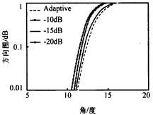
Figure 5 Cumulative probability distribution of four smart antenna systems for 32 users Figure 6 shows the out-of-bounds probability distribution of the system using four smart antennas for capacity expansion when the number of users is lower than the threshold (6dB). Each point in the curve in Figure 6 is 10,000 random users Statistical results of the distribution. With an out-of-bounds probability of 0.01, an adaptive pattern, a side lobe needle beam pattern of -10dB, a side lobe needle beam pattern of -15dB, a side lobe needle beam pattern of -20dB, etc. are used. The capacity expansion of the four smart antenna systems is 6.81, 4.81, 6.62, and 5.66 times that of the omnidirectional antenna system. |
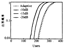
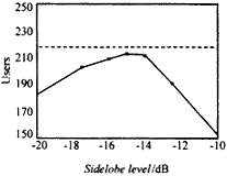
Figure 6: Out-of-bounds probability of the expansion of four smart antennas Figure 7 shows an 8-unit equilateral side-lobe needle beam pattern smart antenna. When the out-of-bounds probability of Eb / N <6 is 0.01, the number of users that can be supported by a smart antenna system with different side-lobe level patterns Curve. The dotted line in the figure is the number of users that the adaptive smart antenna can support: 218. As can be seen from FIG. 7, when the side lobe level is -20dB, the number of users that the system can support is 181. With the needle beam pattern As the side lobe level increases, the system capacity increases. When the side lobe level is -15dB, the number of users that the system can support reaches a maximum: 213, which is only 5 fewer than the system using an adaptive smart antenna. After the level exceeds -15dB, the system capacity will decrease as the side lobe level of the needle beam pattern increases. When the side lobe level is -10dB, the system can support 153 users.
Figure 7 Smart antenna capacity expansion user number ratio side lobe level It can also be found from Figures 6 and 7 that the smart antenna system using the -15dB equal side lobe pattern and the adaptive smart antenna have an approximate capacity expansion. In order to explain this phenomenon, the necessary requirements are given in Figure 8. When the signal origin is 180 degrees, and the other 200 interfering users are randomly distributed, the directional pattern obtained by the adaptive algorithm. As can be seen from FIG. 8, when the number of interferences is much greater than the number of array elements, the directional pattern obtained by the adaptive algorithm (Figure 8 ) And side lobe patterns such as -15 (Figure 3) have similar main lobe width and side lobe level. This phenomenon can be explained by the principle of the adaptive algorithm. When the number of interference is less than the number of array elements, the self-adaptive The algorithm can generate pits to completely suppress the interference. When the number of interference is much greater than the number of array elements, because the interference has spread in all directions of the circle, the adaptive algorithm can no longer suppress interference by forming pits, it can only pass The formation of lower side lobe levels to suppress interference. This conclusion is very important, which shows that when using smart antennas to expand capacity, it may not be necessary to use an adaptive algorithm, only need to select the appropriate side lobe pattern to achieve And expansion capability similar adaptive algorithm.
Figure 8: Adaptive direction with 200 users It can also be seen in Figures 6 and 7 that the performance of smart antenna systems using the -15dB pattern and the -10dB and -20dB patterns is very different, which indicates that choosing different isolateral lobe patterns will significantly affect the expansion of the smart antenna. Capability. Comparing the three equal side lobe patterns in Figure 3 and Figure 4, it can be seen that when the array structure is fixed, the side lobe level is inversely proportional to the main lobe width. The -10dB reverse pattern has a narrow main lobe , But its side lobes are higher and the system performance is reduced; although the -20dB pattern has lower side lobes, because of its wider main lobe width, the system performance is also reduced. So there is no need to pursue too narrow in practical applications The main lobe or the side lobe that is too low should be selected to have an equal side lobe pattern with similar main lobe width and side lobe level as the pattern obtained by the adaptive algorithm. At this time, the performance of the needle beam smart antenna is close to the best. 4. Conclusion This paper studies two different smart antenna systems using adaptive pattern and equal side lobe needle beam pattern. The simulation results of the capacity expansion of these two types of smart antennas to the existing CDMA system are given. It shows that when using smart antennas to expand capacity, it may not be necessary to use an adaptive algorithm, and only need to select a suitable isolateral lobe pattern to achieve capacity expansion similar to that of the adaptive algorithm. The simulation results also show that different isosidelobe patterns are selected. , Will significantly affect the expansion capacity of the smart antenna. So in practical applications, the side lobe pattern with the main lobe width and side lobe level similar to the pattern obtained by the adaptive algorithm should be selected to make the performance of the smart antenna close to the best. |
Dance Floor LED Display features: Dance Floor Led Screen features simple installation and strong applicability. It is suitable for indoor and outdoor use. The bearing capacity can reach 2 tons. The surface is made of PVC material. The surface is frosted. It has waterproof and antiskid functions. The bottom bracket is directly installed without other installation equipment. The base has screw design and the height can be adjusted.
Dancing Floor Led screen effect: interactive Dance Floor Led screen reacts in millisecond when people interact with tile, and the perfect combination of real people and screen. interactive Dance Floor Led screen is divided into intelligent interactive tile screen and radar interactive tile screen. They have their own characteristics in use: intelligent interactive tile screen without external equipment, clean appearance, simple installation, random splicing, radar interactive tile screen with external interactive radar, applicable to glass mutual Moving plank road screen and outdoor bad weather make the interactive floor tile screen perfectly displayed in all application occasions.
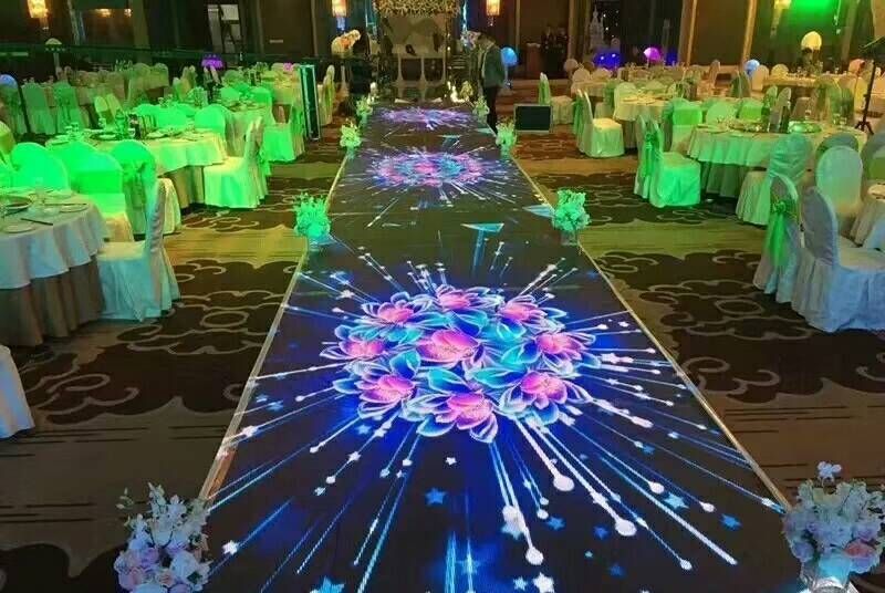
Installation features and precautions: the floor tile screen is installed with a base and adjusting screws to effectively ensure the flatness of the screen body, leaving a certain gap at the bottom for drainage and heat dissipation. Before installing the floor tile screen, the floor should be reserved with a certain depth, which should be flush and beautiful with the floor after installation.
Application scenario: the cabinet size is mainly 500 * 1000mm and 500 * 500mm, mainly used in stage, concert, performance, bar, disco, shopping center and other fields.
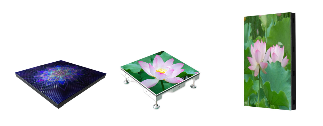
Maintenance: front and rear maintenance, can directly replace a single box and a single module, without removing the adjacent box.
Display effect: highlight, good consistency, no time difference between interaction with people, people and stage display complement each other. Truly achieve the effect of integration of interaction.
Screen principle and structure: the screen has built-in intelligent interactive equipment with many contacts and sensitive sensing. The box body is directly connected with waterproof aviation plug, and the installation is quick.

Smd Screen,Dance Floor Led Display,Led Dancing Floor,Interactive Dance Floor Led Display
Shenzhen Vision Display Technology Co,.LTD , https://www.ledvdi.com
