In real life, magnetic cards are the most common cards used to identify users. Both the International Organization for Standardization and China's national standards have established standards for such storage technologies using magnetic media. Magnetic card technology is widely used by commercial, government, medical and other institutions, but the largest scale is the use of various credit cards, debit cards and other cards issued by banks. The International Organization for Standardization (ISO) has released the international standard for the ISO 7811 series of magnetic cards. Since the release of the first version of the standard in 1995, the content has been revised and added, covering everything from mechanical structures to storage methods and data formats.
In the previous banking system, the work of reading cards was mainly done to the cash register or the ATM and the sales terminal. These devices were provided by the merchants and the maintenance cost was high. All of this changed with the squares that appeared in the United States in 2009. Square payments use very small, inexpensive terminals that are very small, inexpensive and even available to customers for free, using the customer's smartphone for banking transactions. In just two years, this new form of business has grown on a large scale, and a number of similar manufacturers have emerged in China and have successfully launched a series of products. Because this business model is still supported by the online banking platform, this reference design only focuses on the design of the terminal itself.
Hardware system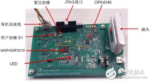
This design consists of hardware and software components, including software on the MCU side and smartphone-side applications (Android platform). As shown in Figure 1, the system hardware consists of an MCU, a power supply circuit, a head signal conditioning circuit, an encryption circuit, and a communication circuit.
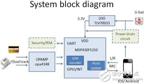
The MCU uses the MSP430F5310, which has a wide power supply range (1.8V to 3.6V), and has very low operating power consumption and standby power consumption. It consumes only 195uA/MHz at 8MHz@3V. With multiple operating modes, only 1.1uA@3V (RAM hold) during standby, a fast start can be achieved in this mode. In addition, the device has a large RAM and a wealth of peripherals, and the timer resources are abundant. These features are well suited to the characteristics of this application that require absolute low power consumption.
2.2 Power supply circuitThere are many choices of power supply circuits, as shown in Figure 1: The headphone interface of the smartphone can be used to obtain the power required for operation, but the limitation of this method is that the hardware of the mobile phone is different, and the output power of the earphone circuit is from several milliwatts. It can vary from tens of milliwatts. In order to make the device work, about 20 milliwatts or more of power output is required, but a considerable number of mobile phone earphone circuits cannot output enough power for the device to use. In order to be compatible with as many mobile phones as possible, it is more practical to provide a high compatibility at a similar cost by incorporating a small lithium battery or a button battery in the device. When the overall power consumption of the device is reduced to the order of a few milliwatts, a small button battery can be used to support enough usage times. The solution in this paper is designed for the power supply through headphones and the use of small lithium batteries. It can be selected according to performance and cost requirements.
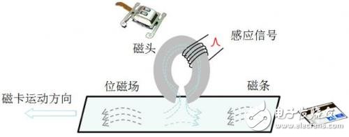
2.3 Introduction of magnetic head and magnetic card 2.3.1 Magnetic headThe core component of the card reading device is the magnetic head. The magnetic head is the key device for converting the magnetic signal into an electrical signal. Only the magnetic signal on the magnetic card can be converted into an electrical signal, and the information stored thereon can be read and used. The magnetic head is mainly composed of a magnetic material and a coil wound thereon. As shown in FIG. 2, when a magnetic strip having a magnetic field passes through the magnetic head, since the magnetic resistance of the magnetic material of the magnetic head is small, the magnetic flux of the magnetic field of the magnetic strip is derived from the magnetic material of the magnetic head. Passing through, thereby inducing an electrical signal in the head coil, this signal can be processed further after being further amplified.
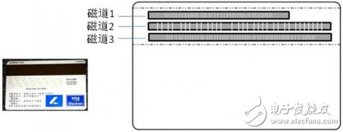
The reading of the magnetic card is similar to that of the widely used tape drive. Both the magnetic card and the magnetic tape use a magnetic field to store the changed signal, and the magnetic field to the electric field is converted by the relative movement of the track and the magnetic head. As shown in Figure 3, according to the standard, there can be up to three tracks on the magnetic card. One of the three tracks is a read-only track, and the third track is a read-write track. The information stored in the track is determined by the standard, and which tracks are used are determined by the actual application requirements. Domestically, bank magnetic cards are mainly credit cards and debit cards. Except for one or two tracks, many credit cards do not use the third track, and most debit cards use the third track.
The magnetic track is covered with magnetic material. When data needs to be written, the magnetic head coil is energized, the current changes according to the signal, and the magnetic field generated by the current magnetizes the magnetic track, which is a reverse operation of reading. This article only covers the read operation and does not introduce the write process. For the bank card, all of the above are digital signals, namely "0" and "1", and the digital signal is represented by the change of the direction of the magnetic field and the change of the frequency.
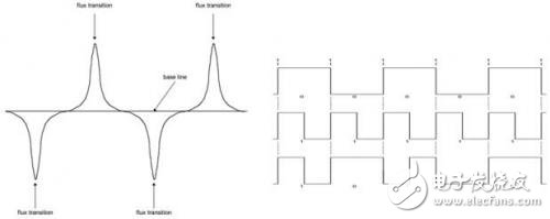
Figure 4 shows the specification of the magnetic stripe signal in ISO-7811. On the left is the distribution of the actual magnetic field strength on the surface of the magnetic strip. It can be seen that the direction of the magnetic field on the magnetic strip is always alternating, that is, the reverse of each data bit is opposite. Further, in order to indicate "0" and "1", the standard also stipulates that the direction of the magnetic field changes once every time to "0" in the unit time, and "1" when the direction of the magnetic field changes twice in the same time. Therefore, the signal coding specified by ISO-7811 is actually based on frequency variation. As shown in the right diagram of Figure 4, each bit carries clock information and does not generate cumulative errors.
Ningbo Autrends International Trade Co.,Ltd. , https://www.ecigarettevapepods.com