 "
" Why can the One Piece ship go so far?
Come learn the driver! ONE PIECE waiting for you to come
â€I have already mentioned how to use discrete components to build the drive circuit of the Buck circuit, such as a triangular wave generator and a level-adjustable circuit. When the circuit design is completed, you need to do it yourself. Measure the waveform of each point, whether it is consistent with your own presets, and verify your design, so that you have a deeper understanding.
Next, I will build on my own circuit design step by step. Follow the steps in the original design, first look at the triangular wave generator:
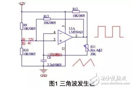
Figure 1 shows the triangular wave generation circuit, which is realized by the charge and discharge principle of the capacitor.
The test waveform is shown in Figure 2: R11, R12, C6 determine the rising edge of the triangle wave, R11, C6 determine the falling edge, assuming C is unchanged, changing R11 can change the frequency of the triangle wave, and from the resistance value Analysis, the rise time is always greater than the fall time; the upper and lower limits of the triangle wave are composed of R9, R10, R13 voltage divider circuit, the waveform is shown in Figure 3.

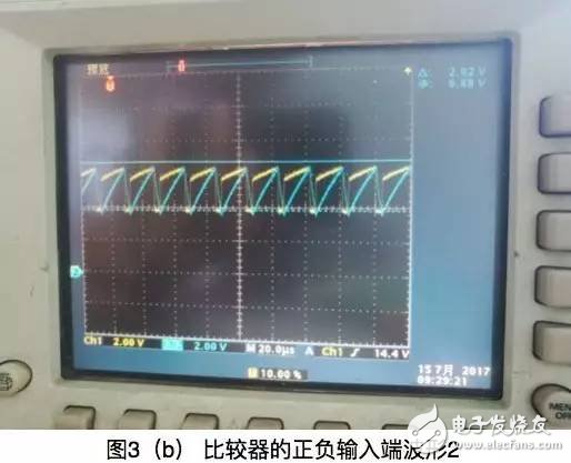
It can be seen from the waveform of Fig. 3 that by adjusting R11, the frequency of the triangle wave can be changed (the yellow is the 5-pin waveform, the blue is the 4-pin waveform), the rising edge of the triangular wave is greater than the falling edge time, when the 5-pin voltage is high Capacitor charging, triangle wave is in the rising edge phase; when the voltage of pin 5 is low, the capacitor discharges and the triangle wave is in the discharge phase, which is consistent with the previous design analysis and achieves the expected effect.
Next, look at the DC adjustable level circuit. The circuit schematic is shown in Figure 4:
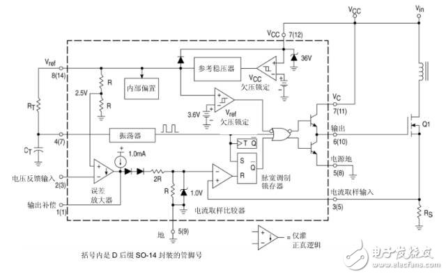
By adjusting the resistance value of R15 and changing the voltage value of V3, the DC level value is changed. Since the emitter of the transistor is followed here, the DC level is about 0.7V larger than V3. The test waveform of the two points is shown in Figure 5:
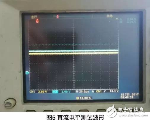
Among them, yellow is V3 voltage, blue is DC level voltage, and the two are always maintained at a voltage difference of 0.6V, which is consistent with the preset.
After the triangle wave circuit and the DC level test are completed, the next two signals are compared and the PWM wave is output. The two waveforms of the comparator are shown in Figure 6:
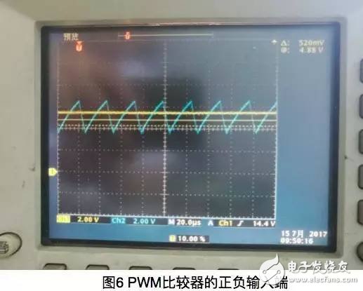
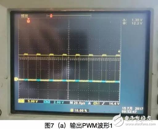
By adjusting the DC level, PWM waves of different duty cycles can be obtained. As shown in Figure 7:
By adjusting the DC level, PWM waves of different duty cycles can be obtained. As shown in Figure 7:
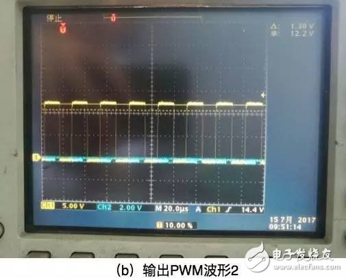
The explanation about the circuit function is almost finished here. It can be seen from the analysis that the output duty cycle waveform is related to the peak current of the sample, so this chip is the peak current control chip, and the other voltage The output feedback loop can be regarded as the upper limit of the comparison of the current feedback signal. The response time of the voltage feedback loop is long, and the integral compensation capacitor is added. Like the PI algorithm, the error can be reduced and the duty cycle modulation tends to be stable. The internal structure of these control chips is similar. After mastering the analysis method of the chip, you can try to analyze the structure of other control chips to facilitate better use of the chip in the future.

There are a few different types of slip rings, but the most common type is called a cap slip ring. Cap slip rings have a cylindrical housing with an internal flange that fits over the end of the shaft. They typically have 6 or 12 channels and are available in a wide range of sizes.
Cap slip rings are used to provide electrical power and signals to and from rotating equipment. The channels on the slip ring allow for the passage of current and/or data signals through the ring. This allows for the rotation of devices such as antennae, radar dishes, and wind turbines without having to interrupt or disconnect the power or signal lines.
Cap slip rings are very reliable and can handle high speeds and heavy loads. They are also easy to install and maintain.
In the modern world, companies are always looking for ways to improve the efficiency of their machines and operations. Oubaibo offers a variety of products that can help improve your machine's performance. Their Cap Slip Ring allows for high-speed rotary unions, while their high-pressure swivel joints can handle even the most strenuous industrial applications. With so many options available, there's sure to be an Oubaibo product that can improve your machine's performance.
Cap Slip Ring,High Speed Rotary Unions,High Pressure Swivel Joints,High Pressure Swivel Joint
Dongguan Oubaibo Technology Co., Ltd. , https://www.sliprobo.com