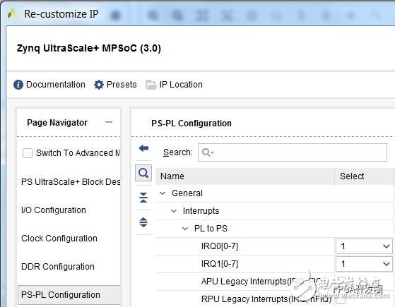
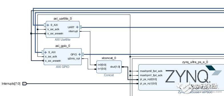
The hardware connection MPSoC can receive two sets of interrupt signals from the PL. In Vivado, it can be opened via PS-PL Configuration -> General -> Interrupts -> PL to PS -> IRQ0/IRQ1.

The corresponding hardware interrupt number is PL PS Group 0: 121-128PL PS Group 1: 136-143
These two sets of interrupt signals can be connected to the interrupt signal of the IP in the IPI or to the logic in Verilog. If there are multiple interrupt sources to be connected to a group of signals, you can use concat to combine multiple signals into a single set of signals and then connect to the IRQ.

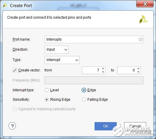
If you want to introduce an interrupt signal from Verilog, you need to right click in the IPI to select Create Port. Port Type is selected as Interrupt.

Hardware and software bridge: device tree
How is the hardware information transmitted to the software system?
The answer to Linux is Device Tree .
The following is the device tree that Device Tree Generator automatically creates for AXI UARTLite in the figure above.
Axi_uartlite_0: serial@a0000000 {clocks = <&misc_clk_0>;compatible = "xlnx,xps-uartlite-1.00.a";current-speed = <115200>;device_type = "serial";interrupt-parent = <&gic>;interrupts = <0 89 1>;port-number = <1>;reg = <0x0 0xa0000000 0x0 0x10000>;xlnx,baudrate = <0x2580>;xlnx,data-bits = <0x8>;xlnx,odd-parity = <0x0> ;xlnx,s-axi-aclk-freq-hz-d = "99.999";xlnx,use-parity = <0x0>;};
Create Device Tree Device tree is a plain text file with a .dts or .dtsi suffix. Of course you can write it from scratch (it doesn't seem to do this), and Xilinx also provides tools to help automate the build.
One way is to use PetaLinux, which is actually a step in petalinux-build. When importing HDF in a PetaLinux project, running petalinux-build will automatically call Device Tree Generator (DTG) to generate a device tree for your project. The user can further modify the file based on the automatically generated file. When modifying, note that the file will be overwritten when the file is regenerated and which will not.
Another way to generate a device tree is to use the SDK. The SDK can load the DTG as a BSP Generator to generate the device tree. The download address for DTG is [ https://github.com/Xilinx/device-tree-xlnx ]. Once downloaded to the local, add the extracted directory to the SDK's Xilinx Tools -> Repositories. Create a new BSP in the SDK, select the device_tree for the BSP type
Note: If it is an SDx tool, the method to load the DTG is Window -> Preference -> Xilinx SDK -> Repositories
The definition of the Interrupt property has two interrupt-related properties in the Device tree, interrupts and interrupt-parents.
Interrupt-parents points to the interrupt controller. There are multiple peripherals in the MPSoC that have interrupt controller properties, namely GIC, GPIO, PCIe.
The parameters after interrupts specify the interrupt number and interrupt attribute.
The meaning of the parameters after interrupts is defined in Device tree bindings interrupts.txt. It should be noted that there is a definition of #interrupt-cells in the properties of the interrupt controller, indicating that the interrupts parameter requires several 32-bit characters. The common situation is 1 to 3. In the case of 1 Cell, only the interrupt number is filled in. In the case of 2 Cells, the interrupt number and trigger condition are filled in. This is the case with the GPIO Controller.
The ARM GIC uses 3 Cells:
The first cell is 0, indicating the type of interrupt: 0 for SPI interrupts, 1 for PPI interrupts. The PL to PS interrupt is SPI, so fill in 0.
The second Cell indicates the interrupt number and the third Cell indicates the interrupt trigger mode.
ARM GIC v3 Interrupt Cell Description, from arm, gic-v3.txt
The 1st cell is the interrupt type; 0 for SPI interrupts, 1 for PPIinterrupts. Other values ​​are reserved for future use.
The 2nd cell contains the interrupt number for the interrupt type. SPI interrupts are in the range [0-987]. PPI interrupts are in the range [0-15].
The 3rd cell is the flags, encoded as follows:bits[3:0] trigger type and level flags.1 = edge triggered4 = level triggered
The interrupt number is determined . The interrupt number of the interrupts in the Device tree, please fill in the hardware hardware interrupt number - 32
The interrupted driver PetaLinux comes with an example of an interrupt service routine.
You can create an example program with the command petalinux-create -t ​​modules -n mymodule.
The statement related to the registered IRQ interrupt number is: /* Get IRQ for the device */r_irq = platform_get_resource(pdev, IORESOURCE_IRQ, 0); if (!r_irq) {dev_info(dev, "no IRQ found"); dev_info( Dev, "mymodule at 0x%08x mapped to 0x%08x", (unsigned int __force) lp->mem_start, (unsigned int __force) lp->base_addr);return 0;}lp->irq = r_irq->start; Rc = request_irq(lp->irq, &mymodule_irq, 0, DRIVER_NAME, lp);if (rc) {dev_err(dev, "testmodule: Could not allocate interrupt %d.",lp->irq);goto error3;}
Note that the above program retrieves the interrupt by reading dts and then assigns the operating system a virtual interrupt number. The previous registration interrupt number was manually filled in the C code with the interrupt number. Now this method is not feasible. Please use the virtual interrupt number method.
Remoter Controller,Remote Control,Wireless Remote, Universal Remote Control,universal remote
NINGBO COWELL ELECTRONICS & TECHNOLOGY CO., LTD , https://www.cowellsocket.com