The increased number of voltage input rails to power point-of-load DSPs, ASICs, FPGAs, and microprocessors makes power supply design more challenging. In particular, infrastructure, industrial and factory automation equipment is becoming more sensitive to noise and other unpredictable events due to increased system power and operating frequency requirements. For example, incorrect input voltage at system startup can cause system latch-up, reliability problems, and even system failure.
This article discusses how to configure various voltage output tracking and sequencing options for an FPGA or microprocessor to help enable proper startup and shutdown of sensitive multi-rail systems. We will also analyze the ratio and synchronous tracking settings used to prevent the FPGA's built-in electrostatic discharge diode (ESD) from being biased or overstressed during rising and falling outputs. These configurations can significantly improve system reliability, which is important for ensuring productivity and uptime for a wide range of infrastructure systems and industrial equipment on the factory floor.
System Configuration
Figure 1 shows a typical application circuit configuration for an FPGA. From the 3.3V highest input rail to the 2.5V second input rail, we found a set of back-to-back ESD diode configurations acting as an internal protection circuit. Another set of back-to-back ESD diode configurations is from the second input rail to the third input rail.
Figure 1. FPGA Input Block Diagram
Let's assume a situation where the highest input rail (3.3V in this example) starts up first. It then pre-biases the 2.5V output rail to about 1.9V and the 1.8V rail to 1.2V. Similarly, if the 1.8V rail starts first, it pre-biases the 2.5V and 3.3V rails. In either case, the ESD diode must conduct during startup. Figure 2 shows the voltage signal on the 3.3V input rail and its signal sent to the 2.5V rail before startup. The charging current through the ESD diode depends on the startup slew rate, the 2.5V output capacitor, and any load. Performing the same start-up scenario with a 1.8V output rail shows a similar voltage signal.

Figure 2. Startup Waveforms for 3.3V and 2.5V Prebias
Whenever an ESD diode conducts, its reliability degrades. Figure 3 shows what happens to the 3.3V and 2.5V rails when the 2.5V input source is not programmed with pre-bias start-up. As you can see, the FPGA's built-in ESD diodes are stressed at startup from the 2.5V rail. Therefore, using a power supply with pre-bias start-up avoids this problem and prevents possible latch-up of the system. Proper configuration of the buck regulator's output voltage tracking ensures proper soft-start of all system power rails together and prevents ESD diodes from conducting. This simple step improves system reliability and avoids any accidental system power latch-up.

Figure 3. Startup Waveforms for 3.3V and 2.5V
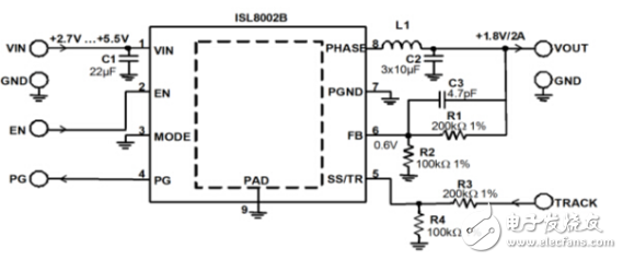
Figure 4 shows a typical application circuit for a 2A DC/DC converter with an input voltage range of 2.7V - 5.5V. Only a few peripheral components are used, including the required resistors, capacitors, and inductors. The converter integrates compensation circuits and power MOSFETs to ensure design reliability, minimum component count and high efficiency up to 95%.

Figure 4. Typical application schematic of ISL8002B
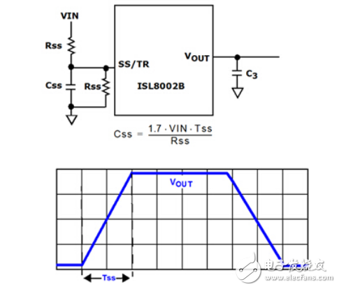
Pin 5 of the converter provides both soft-start (SS) and output tracking (TR) functions. When this pin is tied high, the soft-start time is internally set to 1ms. However, various soft-start schemes can be implemented using peripheral components. Figure 5 shows how to use the SS/TR function to program the external soft-start time.

Figure 5. External Soft-Start Configuration
The soft-start time can be adjusted by setting the soft-start resistor RSS and capacitor CSS. The corresponding approximate relationship is shown in Equation 1:

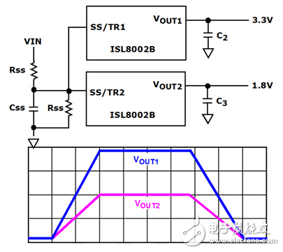
The soft-start feature can also be configured to track other outputs. Figure 6 shows the ratio tracking configuration of Vout1-Vout2.

Figure 6. Ratio Tracking of Vout1-Vout2
In addition, both output voltages can be raised simultaneously by connecting the two SS/TRs together. Similarly, the shutdown functions can also ratio-track each other, as does the soft-start time described in Equation 1.
The synchronization tracking configuration is shown in Figure 7. Just add a resistive divider with the same ratio as its output voltage sense divider in the feedback loop. In this case, all output voltages rise at the same voltage and slope according to the main rail. In general, all other output rails should track the highest voltage rail. Each output will then branch after reaching its stable point. The built-in ESD diodes of Figure 1 are prevented from conducting or forward biasing by well-controlled startup and shutdown of all output rails. Most importantly, this design technique prevents system reliability degradation, latch-up, and worse: system failure.
Figure 7. Synchronous tracking of Vout1 - Vout2
concluding remarks
Integrated FET-style step-down regulators, such as the ISL8002B, provide a number of easy-to-use solutions for voltage tracking during power-up and power-down. Almost any system voltage tracking requirement can be configured using the circuits discussed in this article. These configurations are not limited to two regulators, as they can be used for any number of voltage rails in the system. Just tie all SS/TR pins together for ratio tracking. A resistive voltage divider can also be used to program the system for synchronous tracking. Either ratio tracking or synchronous tracking methods prevent the ESD diodes from being unnecessarily stressed, thereby increasing the overall reliability of the system.
Intel I5 Laptop is the one of the important high cpu processors, another ones are i3, i7, i9. We can do 2th, 4th, 5th, 6th, 8th, 10th, 11th or 12th. How to choose a best suitable one? If you do heavier jobs, like interior design, music or video editing, even engineering drawing, etc, 15.6 inch Intel I5 11th Generation Laptop or Intel I5 10th Generation Laptop is a better choice for you. If you focus on portability, Laptop 14 Inch I5 11th generation is a good option. Of course, Intel i7 11th Generation Laptop or 1650 graphics card laptop also available.
Someone may worry the custom one quality, that`s cause that lack of custom Student Laptop knowledge, so just keep reading so that know deep in this field. Frankly speaking, the technical skill is totally mature, no matter hardware or software or craft. You can see nearly no difference when check the oem laptop and brand one in person. To support clients and be confident with our product, provide sample for every clients.
Any other special requirements, you can just contact us freely or email us and share the exact details about what you need, thus right and valuable information sended in 1 working day.
Intel I5 Laptop,Intel I5 11th Generation Laptop,Intel I5 10th Generation Laptop,Gtx 1650 i5 10th Gen,Intel I5 Laptop Price
Henan Shuyi Electronics Co., Ltd. , https://www.shuyiminipc.com