Low dropout regulators (LDOs) can be used to power high speed clocks, analog to digital converters, digital to analog converters, voltage controlled oscillators, and phase-locked loops. Noise is extremely important to designers of high performance analog circuits. The key to reducing noise is to keep the LDO noise gain close to unity gain without affecting AC performance or DC closed-loop gain.
This article describes how a simple RC network can reduce the output noise of an adjustable output low dropout regulator. This article demonstrates the effectiveness of this simple method through experimental data. Although the primary purpose of the RC network is to reduce noise, it also improves power supply rejection and load transient response.
Figure 1 shows a simplified block diagram of a typical adjustable output LDO. The output voltage, VOUT, is equal to the product of the reference voltage and the DC closed-loop gain of the error amplifier: VOUT = VR × (1 + R1/R2), where (1 + R1/R2) is the DC closed-loop gain of the error amplifier.
The error amplifier noise VN and the reference voltage noise VRN are amplified by the same multiple, causing the output noise to increase in proportion to the set output voltage. This makes the noise on the output voltage higher than the reference voltage but less than 2 times, and the output noise is moderately increased, but even this modest increase in sensitive applications may be unacceptable.
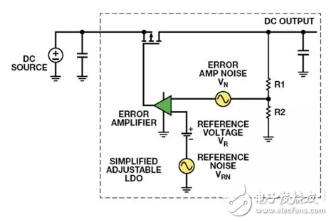
Figure 1. Simplified block diagram of an adjustable LDO showing an internal noise source
The main noise source for LDOs is the internal reference and error amplifier. Today's devices operate with internal bias currents of a few hundred nA or less, enabling quiescent currents of up to 15μA. These small currents require bias resistors of up to 1 GΩ, making the error amplifier and reference circuit more noisy than discrete deployments. A typical LDO uses a resistor divider to set the output voltage, so the noise gain is equal to the AC closed-loop gain, and the result is the same as the DC closed-loop gain.
Reduce LDO noiseTwo main ways to reduce LDO noise are to filter the reference voltage and reduce the noise gain of the error amplifier. Some LDOs can use an external capacitor to filter the reference voltage. In fact, many so-called ultra-low noise LDOs require the use of external noise reduction capacitors to achieve their low noise performance. The disadvantage of this technique is that the error amplifier noise and any residual reference voltage noise will still be amplified by the AC closed loop gain. This makes the noise proportional to the output voltage.
Reducing the noise gain of the error amplifier allows the output noise of the LDO to not increase significantly as the output voltage rises. Unfortunately, this is not feasible for a fixed output LDO because the feedback node is not readily available. Fortunately, however, this node is readily available in an adjustable output LDO.
Figure 2 shows an adjustable output LDO where R1 and R2 set the output voltage. A network of R3 and C1 reduces the AC gain of the error amplifier. To ensure the stability of the LDO with low phase margin (or non-unit gain stability), select R3 to set the high frequency gain of the amplifier to around 1.1. To reduce the noise in the 1/f area, select C1 to set the low frequency zero point below 10 Hz.
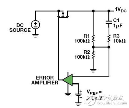
Figure 2. Simple RC network with reduced adjustable LDO noise gain
Figure 3 compares the AC closed-loop gain (whose noise reduction network is properly designed) to the open-loop gain and the unmodified closed-loop gain. With a noise reduction network, the AC gain is close to unity gain over most of the bandwidth, so the reference voltage noise and error amplifier noise amplification is less.
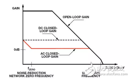
Figure 3. LDO loop gain versus frequency (with noise reduction network)
Figure 4 shows the effect of the noise reduction network on the ADP125 LDO noise spectral density. This curve compares the noise spectral density at 4 V and the noise spectral density per unit gain with and without a noise reduction network.
It can be seen that the noise performance is greatly improved in the range of 20 Hz to 2 kHz. Above the zeros composed of R1 and C1, the noise characteristics of the noise reduction network are basically the same as those of the unity gain. The noise spectral density curve is fused above 20 kHz because the error amplifier's closed-loop gain intersects the open-loop gain and cannot further reduce the noise gain.
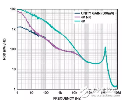
Figure 4. Adjustable Output LDO ADP125 Noise Spectral Density
The power supply rejection ratio (PSRR) in this frequency range is also improved. The PSRR measurement circuit suppresses the external signals (noise and ripple) present at the power supply input, so that these interference signals do not destroy the output of the circuit. The PSRR is defined as: PSRR = VEIN/VEOUT. This can also be expressed in dB: PSR = 20 × log(VEIN/VEOUT), where VEIN and VEOUT are the external signals present at the input and output.
Improve PSRAnother advantage of using a noise reduction network to reduce the output noise of the adjustable output LDO is to improve the low frequency PSR. R1, R3, and C1 in Fig. 2 form a lead-lag network with a zero at approximately 1/(R1 × C1) and a pole at approximately 1/(R3 × C1). The lead-lag network provides a feedforward function for the compensation loop, thus improving the PSR. For frequencies below the closed loop gain and open loop gain fusion, if the amount of improvement is expressed in dB, the value is approximately 20 × log (1 + R1/R3).
Figure 5 shows the effect of the noise reduction network on the adjustable output LDOADP7102. If the output is 9 V, then R1 = 64 kΩ, R2 = 10 kΩ, R3 = 1 kΩ, and C1 = 1 μF. The zero point established by R1 and C1 at approximately 2.5 Hz demonstrates an improvement in PSRR above 10 Hz. The total PSRR increases by approximately 17 dB from 100 Hz to 1 kHz. The improvement is not reduced until about 20 kHz; where the open loop gain and closed loop gain are combined.
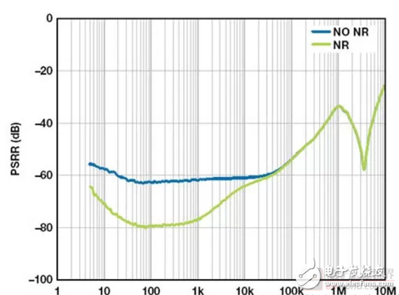
Figure 5. Adjustable output of the LDOADP7102/ADP7104 with and without a noise reduction network
The noise reduction network also improves the transient load response of the LDO. Similarly, R1, R3, and C1 perform the feedforward function of the compensation loop. The high-frequency component of the load transient—detected by an un-attenuated error amplifier—allows the error amplifier to respond quickly to load transients. Figure 6 shows the ADP125 load transient response with and without a noise reduction network. With a noise reduction network, the LDO can respond to load transients within 50μs without 500 μs when using a noise reduction network
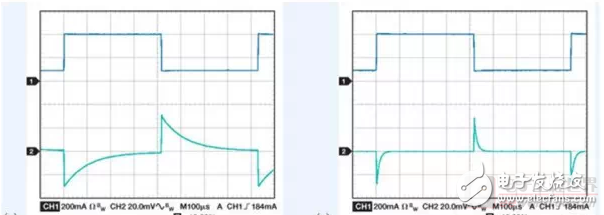
Figure 6. Transient load response of the adjustable output LDO ADP125 (a) no noise reduction network used (b) noise reduction network
One disadvantage of noise reduction networks is that it greatly increases startup time. Figure 7 shows the ADP125 boot time when using and not using a noise reduction network. The normal startup time is approximately 600 μs. If C1 = 10 nF, the start-up time is increased to 6 ms; if C1 = 1 μF, it is increased to 600 ms. For applications where the LDO is no longer switched after the circuit is fully powered up, the increase in startup time should not be an issue.
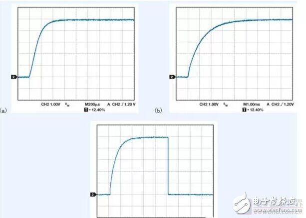
Figure 7. Adjustable Output LDO ADP125 Startup Time (a) No Noise Reduction Network (b) Noise Reduction Network, C1=10 nF
(c) Using a noise reduction network, C1=1 μF
By adding a simple RC noise reduction network, the noise, power supply rejection, and transient performance of the adjustable output LDO can be significantly improved for high-speed clocks, analog-to-digital converters, digital-to-analog converters, voltage-controlled oscillators, and phase-locked loops. Equal noise-sensitive applications bring great advantages.
LDOs such as the ADP125, ADP171, ADP1741, ADP1753, ADP1755, ADP7102, ADP7104, and ADP7105 all have this common architecture and will greatly benefit from the use of noise reduction networks. This technique can be used in an LDO architecture similar to that shown in Figure 2, where both the reference voltage noise and the error amplifier noise are amplified by the DC closed-loop gain, so the output noise is proportional to the output voltage.
Newer ultra-low noise LDOs, such as the ADM7151, do not benefit from this noise reduction network because the architecture uses a unity-gain LDO error amplifier, so the reference voltage is equal to the output voltage. In addition, the internal reference filter pole is below 1 Hz, which greatly filters the reference voltage and eliminates almost all of the reference noise effects.
Telecom systems is the exchange of information over significant distances by electronic means. A complete, single telecommunications circuit consists of two stations, each equipped with a transmitter and a receiver. And we will offer the basic telecom products which you may familiar in your life to build up the telecom systems.
From Data center with a floor standing cabinets, you may get your sign out .For distribution outdoor, you may need a waterproof Distribution Box to exchange the singals. Meanwhile, you may have a terminal block with 10 pair disconnection Krone Module and lighting protectors(LSA single pair type or STB module). When you distribute in house, there are more products in application like voice patch panels, keystone jacks, face plate, 3M connectors(like UY connectors), AMP picapond connector, wall outlets, surface mount box, and so on. Sure there is a must to get the right tool to finish operations, kinds of tools for selection: Insertion tools, punch tool, crimping tool, wire cutter, cable stripper. Hot sale for krone insertion tool, RJ45 crimping tools, Ericsson punch down tool, AMP picabond ratechet crimper, Coaxial cable crimping tool .
We insist on compact size to ensure an easy but smart and reliable installation in every product of the telecom systems we offer. That is the final aim we work on solution, to make it perfect we also provide OEM service to satisfy your special demand. Till now, we have successfully take part in many Telecom projects in Russia, Sri Lanka, Greece, Ecuador, ect.. We have full experience in such tenders for building up telecom systems.
We keep on working just like the Cable Ring Managers to keep everything Orderly, Fast and Effective. Believe us and we will help you to be the winner !

Outdoor Distribution Box, LSA Krone Module, Mounting Frame, STB Module, Picabond Connector , Crimping Tool
NINGBO YULIANG TELECOM MUNICATIONS EQUIPMENT CO.,LTD. , https://www.yltelecom.com