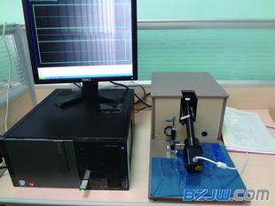
FSM-6000LE
Surface stress meter inspection operation guide
Effective date 2015-11-27 Document version B0 A total of 1 page file number is proposed for approval 1,
The instrument is plugged into a power source and the small bulb is illuminated by a transformer;
2,
Drop a few drops of refractive index oil on the bottom surface of the prism;

3,
Determining the immersion tin surface of the glass to be tested, and gently placing the instrument on the surface;
4,
Measuring point is at the long side
10
0
The distance of mm is two parallel lines parallel to the long side, and intersects the diagonal line at 4 points. These 4 points and the geometric center point of the product are the measurement points;
5,
If the short side length of the product is less than 300mm, then the two parallel lines parallel to the short side and the center line intersect at 2 points at a distance of 100mm from the short side. These two points and the geometric center point of the product are measured. point;
6,
Adjust the eyepiece first so that the reticle is clearly visible in the field of view;
7,
Adjust the position of the small bulb and shutter to the highest position, and then gradually lower the height of the bulb (each adjustment of the bulb is about half a week). After the adjustment, slowly adjust the mirror adjustment knob back and forth and pay attention to observe Repeat the above steps for the eyepiece field of view until a clear step pattern is seen in the field of view of the eyepiece;
8,
Adjust the micrometer eyepiece so that the coordinate line in the field of view is aligned with the upper end of the horizontal axis first step. At this time, the reading on the micrometer eyepiece is read and recorded, and then the horizontal axis of the coordinate line is moved to the lower end of the step. The reading on the micrometer eyepiece is inferior to the last reading (if the second reading is less than the first reading, first add the second reading to 100 and then the difference between the first reading and the first reading. Sometimes there are multiple steps in the field of view, then the clearest group in the field of view is taken to measure), and the difference is the measured step height d;
9,
Multiplying the instrument constant K by the step height d is the surface stress value of the glass to be tested.
10.
The basic formula for calculation is:
F=
d
×K
F
The stress value of the glass to be tested (MPa);
d
Step height read from the micrometer eyepiece (mm)
K
Instrument constant (take 880 MPa/mm).
11,
The measurement result is an arithmetic mean of the measured values ​​of the respective measurement points;
12.
The surface stress of tempered glass should not be less than 90 Mpa;
13,
Taking the product as a sample, take 3 samples for testing. When all the samples meet the requirements, the two samples are not qualified.
When two samples meet, three more samples are added, and if all three meet the requirements, they are qualified.