With the rapid development of computer technology and network technology, the development trend of the public security and security industry must be comprehensive digital and networked. Traditional analog CCTV surveillance systems have many limitations: limited transmission distance, inability to network, and the storage of analog video signal data consumes a large amount of storage media (such as video tapes), which is very cumbersome when querying for evidence.
The video monitoring system based on the personal computer has strong terminal functions, but the stability is not good. The video front end (such as the video signal acquisition, compression, and communication of voltage coupling components) is complicated and the reliability is not high. The network monitoring system based on embedded Linux video does not need a personal computer for processing analog video signals. Instead, the video server is built with an embedded Web server and uses an embedded real-time multitasking operating system.
Because the video compression and Web functions are centralized in a small device, you can connect directly to the LAN, plug and watch, save complicated cables, easy to install (just need to set an IP address), users do not need to install any Hardware devices that can be viewed with just a browser.
The embedded network-based video network monitoring system connects the embedded Linux system to the Web, that is, the video server has an embedded Web server built in. The video signal transmitted by the camera is digitized and compressed by the high-efficiency compression chip, and transmitted to the built-in Web through the internal bus. On the server.
1 system overall framework
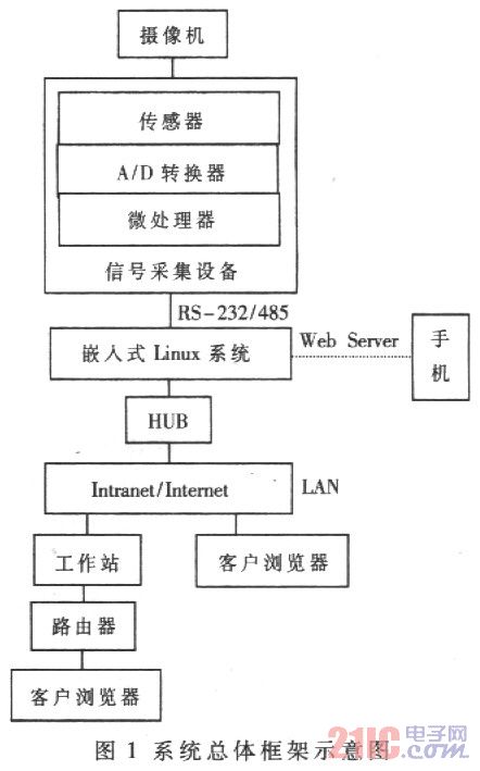
The embedded Linux video network monitoring system is an organic combination of electrical and electronic devices, computer hardware and software, and network, communication, etc. It is characterized by intelligence, networking, and interactivity, and the structure is relatively complicated. If the content and form of the OSI seven-layer model are used, the corresponding data acquisition control module hardware and application software and application environment can be organically combined to form a unified system overall framework. The overall framework of the system is shown in Figure 1.
This article refers to the address: http://

System overall framework diagram
After the video signal transmitted by the camera is digitized, it is compressed and sent to the built-in Web server through RS-232/RS485. The 10/100M Ethernet port of the embedded LJnux system is connected to the Internet network, and the live signal is sent to the customer. end. The core of the entire system is the embedded Linux system. After the monitoring system is started, the embedded Linux system starts the Web Server service program and receives the request from the authorized client browser. The Web Server will complete the corresponding monitoring according to the communication protocol.
2 system implementation
2.1 Hardware platform design
Based on the open embedded Linux source code, the system writes the corresponding Bootloader program according to the designed embedded target board, and then cuts out the appropriate kernel and file system. The target platform CPU uses the ColdFire embedded processor MFC5272 produced by Motorola. The MFC5272 uses the ColdFire V2 variable-length RISC processor core and DigltalIDNA technology to achieve 63Dlnrystone2.1MIPS with excellent processing power at 66MHz clock.
The internal SIM (System IntegratedModule) unit integrates a wide range of general-purpose modules, enabling two RS-232 serial ports and one USB Slave interface with few peripheral chips. The MFC5272 also embeds an FEC (Fast Ethernet Controller) and expands the LXT97l off-chip to easily implement a 100/10 BaseT Ethernet interface. The ability to seamlessly interface with commonly used peripherals such as SDRAM and ISDN transceivers simplifies peripheral circuit design and reduces product cost, size and power consumption.
2.2 Software Design and Implementation
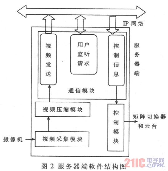
The video surveillance system software structure uses a browser, server (B / S) network model, that is, the client makes a request to the server through the Web, the server responds to the request and performs the corresponding task (such as sending the group to the client) Broadcast address, image format, compression format, etc.), after the connection is established, the controlled point can be monitored on the client side, thereby realizing remote network monitoring. The software structure of the server (Web Servei) end, that is, the site monitoring point includes an acquisition module, a compression coding module, a network communication module, a control module, and the like, as shown in FIG. 2 .

2.2.1 Video acquisition module design
Since the camera gets an analog video signal that cannot be used directly by the computer, in order for the video to be transmitted over the network, it must first be digitized. The video capture card selected by this system is Conexant's Bt848 card. This card does not require any local cache to store video pixel data. It can also make full use of the high bandwidth and inherent multimedia functions based on PCI bus system, and can cooperate with other multimedia devices. Implement interoperability.
In the whole system, because the speed of video capture is usually higher than the speed at which the application software obtains data and processes it, in order to ensure the continuity of the video data, a three-cache structure is adopted, and the cache A is the target address of the Bt848 video capture, in the RISC instruction. Under the direct control, the collected data is first stored in this cache; B and C form a ping-pong structure for cyclic use, when a certain frame of data is collected, an interrupt is generated, and the data of the cache A is copied in the interrupt service program. Go to cache B (or C) and then capture the next frame, after the next frame of data is collected. The data in cache A is then copied into cache C (or B), and the latest image is read from cache B or C when the application needs data. Cache B and C are used interchangeably to ensure that the operation of the application to read data from the cache and the operation of the driver to write data to the cache do not conflict, avoiding data corruption and delay.
2.2.2 Design of video compression coding
This design selects the object-based MPEG-4 video coding technology. First, the input VOP sequence of arbitrary shape is coded by block-based hybrid coding technology. The processing order is first intra-frame VOP, post-interframe VOP, and bi-directional predictive VOP.
After encoding the shape information of the VOP, samples of the VOP of arbitrary shape are obtained, and each VOP is divided into disjoint macroblocks by a macroblock raster, and each macroblock contains four 8×8 pixel blocks for motion estimation. And compensation and texture coding. The encoded VOP frame is stored in the VOP frame memory. The motion vector is calculated between the current VOP frame and the encoded VOP frame. The motion compensated prediction error is calculated for the block or macroblock to be encoded. The motion compensated predicted I-VOP and error are encoded by 8x8 block DCT, and the DCP coefficients are quantized, followed by run length coding and entropy coding.
Finally, shape, motion, and texture information are combined into a VOL bitstream output. This encoding method allows the user to modify, add or relocate objects in a video scene, and even convert the behavior of objects in the scene. For different bandwidth and computational complexity requirements, it is not necessary to separately code for each case, the same video bitstream can be used, and different parameters are used to select different layers for flexibility. It can still provide a coherent video image when there is network congestion or packet loss. The video compression encoding process stores the encoded video into the encoded video buffer queue, and activates or waits for the corresponding processing of the live process and the storage management process.
2.2.3 Network communication module design
The network communication module is the main part of the system and it contains three data channels: the listening channel, the control channel and the video data channel. The monitor channel is used to transmit command data for controlling the front-end device; the video data channel is used to transmit video data of each group. The three channels use different communication ports, so each channel transmits data independently of each other. The design and development of the network communication module is realized through the network programming interface (Windows Socket, Winsoek for short). Follow the system browser, the server's network transfer model. On the server side, a SOCKET type listening socket and a control socket are established; a SOCKET type request socket and a control socket are established on the client side, and these are all encapsulated and transmitted data by using the ICP protocol.
In addition, a multicast class (CMuhieast) is used on both the server and client side, which is a class specifically packaged for video transmission. Derived from CObject, which defines the socket and group sockets for sending and receiving video data with SOCKET type, which realizes the transmission of UDP protocol-encapsulated video data packets by multicast communication. The IP network data communication process in the system is shown in Figure 3.

IP network data communication process
The procedure for establishing a listening socket and a control socket on the server side is given below.
......
Int ret="O":
BOOL bFlag="TRUE"://Set the socket to a reusable port address
Ret=setsoekopt(IInfo.listenSocket,SOL_SOCKET,SO_REUSE
ADDR, (char)*&bFlag,sizeof(bFlag));
SOCKADDR_IN sockAddr;
Char*addr=severaddr.GetBuffer(0); //Define the listening socket
//the address of
sockAddr.sin_family=AF_INET;
sockAddr.sin_addr.S_un.S_addr
=inet_addr(addr);
sockAddr.sin_port=htons(PORT):
If(bind(IInfo.1istenSoeket,(LPSOCKADDR)
2.2.4 Control module design and development
The control module implements user control of front-end devices such as lens, pan/tilt and screen switching. After receiving the control information frame sent by the client center monitoring terminal, the server analyzes and parses it, and sends it to each corresponding control component interface to implement corresponding control.
3 Experimental results
Connect the web server of the video surveillance system to the LAN, then access the Internet and assign an IP address to the web server. In the user terminal, since it is inconvenient to use a normal browser to display a single screen, using Microsoft's VC6.0 with Microsoft's browser control, it takes only a few minutes to complete a multi-screen browser software. Enter the address of the video server directly in the address bar of the browser, and you can play remote real-time stable and smooth images in the browser page, and achieve good monitoring results.
The web server of the network monitoring system based on embedded Linux video is directly connected to the network, without the limitation of cable length and signal attenuation. At the same time, the network has no distance concept, completely abandoning the concept of the region and expanding the control area. And because video compression and Web functions are concentrated in a small device, directly connected to the LAN or WAN, plug and watch, the system's real-time, stability, reliability is greatly improved, no need for special management, very suitable for no The environment in which people are duty. With the rapid development of computer technology and network technology, people's requirements for video surveillance systems will become higher and higher. It is believed that the system has broad application prospects in e-commerce, video conferencing, remote monitoring, distance learning, telemedicine, water conservancy and power monitoring.
High Frequency Inverter,High Frequency Power Inverter,high frequency pure sine wave inverter ,high frequency sine wave inverter
SUZHOU DEVELPOWER ENERGY EQUIPMENT CO.,LTD , https://www.fisoph-power.com