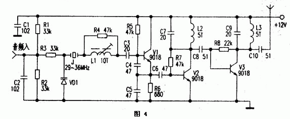
Figure 4 shows the crystal transmitter circuit. J. in the circuit. , VD1, L1, C3 ~ C5, V1 make up the crystal oscillation circuit. Because quartz crystal J has good frequency stability and is less affected by temperature, it is widely used in cordless phones and AV modulators. Vl is a 29 ~ 36MHz crystal oscillating transistor. The emitter output contains rich harmonic components. After being amplified by V2, the collector is composed of C7 and L2. The network that resonates at 88-108MHz selects a triple frequency signal (87 ~ 108MHz) Signal is the strongest), and then amplified by V3; L3, C9 frequency selection to get a more ideal frequency band signal. The process of frequency modulation is such that the change of the audio voltage causes the change of the capacitance between the poles of VD1; because VD1 is connected in series with the crystal J, the frequency of the crystal's vibration fan also changes slightly. After three times the frequency, the frequency deviation is 29-36MHz 3 times the crystal frequency deviation. In practical application, in order to obtain a suitable modulation degree, a quartz crystal or a ceramic vibrator with a large modulation frequency deviation can be selected, or a 6-12 frequency multiplication circuit with a slightly complicated circuit can be used. If the input audio signal is weak; a primary voltage amplifier circuit can be added.
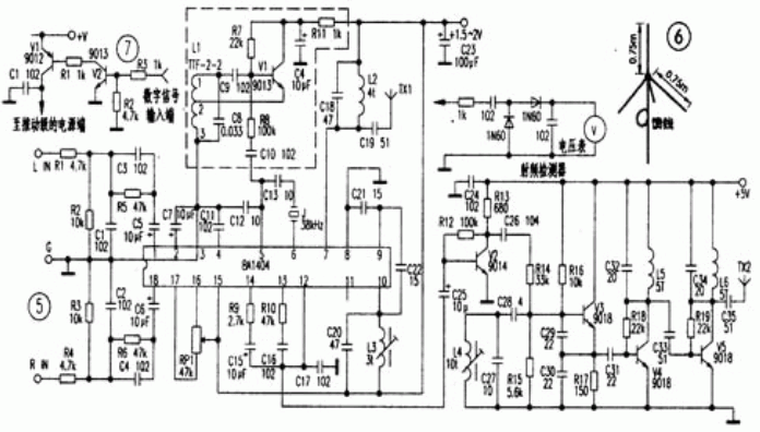
Because the 1.5km FM transmitter (see Figure 1) uses a capacitive three-point oscillator, when the antenna parameters change slightly, the frequency running phenomenon will occur. Furthermore, because it is a single-tube self-oscillation emission, the operating current is large. After a few seconds to a few minutes, the temperature rise of the transistor causes the capacitance between the poles to change, which also brings about a change in the oscillation frequency (generally, the oscillation frequency is reduced), and sometimes the frequency drift reaches 0.2--1MHz. When used as FM broadcast or remote remote alarm, the working reliability is poor, but there are few components, low cost, easy debugging, suitable for junior enthusiasts to launch experiments. The 2km FM transmitter (see Figure 2 in the previous issue) uses three stages of oscillation, frequency doubling, and power amplification. The stages are relatively independent, and the frequency stability is better than the 1.5km transmitter launched by a single-tube self-excited oscillation. After a minute, there is still a frequency drift of 0.2-0.4MHz. This is mainly due to the large operating current of V3 and the temperature rise, which causes the capacitance between the poles to change. This change causes the resonance network composed of C8 and L2 through C9. The parameter changes, and the increase of V2 temperature also causes the parameters of the resonant network composed of C8 and L2 to change. This change is transmitted to the main vibration level composed of C3, C4, L1, C5, C6, V1, etc. through C7, and finally oscillates. The frequency also changes (in general, the oscillation frequency is also reduced). During the experiment, the heat dissipation of the transistor can be strengthened, the coupling between the stages can be reduced, and the capacity of C9 and C7 can be reduced. At the same time, the transistor, resistor, Capacitance, etc., but the frequency drift is still serious. The wireless headphone transmitter shown in Figure 3 of the previous issue, due to the use of an improved capacitive three-point oscillator, is more stable in frequency than the transmitter shown in Figures 1 and 2, and the fidelity requirements for TV wireless headphones are not very high. The occasion is very suitable. The crystal oscillator transmitter shown in Figure 4 in the previous issue uses a crystal, so the frequency stability is very good, but when applied to FM broadcasting and wireless headphones, the frequency deviation of the modulation is much smaller than that of the LC oscillator. When the volume is low, the sound is not round, and it is generally more suitable for circuits such as cordless phones and walkie-talkies with small frequency deviation. Acoustic meter vibrators have been widely used in various wireless remote control and wireless data transmission equipment transmitters, but acoustic table vibrators with frequencies of 88 ~ 108MHz are difficult to purchase, and the production of various frequency synthesis transmitters with excellent performance is more troublesome. Interested parties can refer to (Electronic News) No. 41, 2000, Fifth Edition (Analysis of the Modulation Unit Circuit of Digital Frequency Synthesizer for TGF-10 FM Broadcast Transmitter), this broadcast-grade transmitter uses the universal Motorola frequency synthesizer The chip MCl45152P is used as the core, and a high stability frequency of 84 ~ 108MHz can be obtained through an external dial switch. FM stereo transmitter (see Figure 5 for the circuit) The core device of this circuit is the stereo special chip BAl404. Many FM stereo modules are made by encapsulating BAl404 and peripheral components in a plastic or metal casing, only exposing the power input, audio input, and RF output leads. As long as you understand BAl404, you will know what is going on inside the FM stereo module . The stereo audio signal from the audio source is coupled to BAl404 via a network composed of R1, R2, R5, C1, C3, C5 (R4, R3, R6, C2, C4, C6). It is amplified by the internal left (right) channel of the IC, and then balanced modulation. The modulated composite signal is output from the 14th pin of the IC, and the pilot signal on the 13th pin is formed by B9, C15, B10, C16, C17 The mixed signal of the network is mixed, and the mixed signal after mixing enters the 12 pins of the IC. The contrasted ⑧, ⑨, ⑩ pins, C20--C22 and the capacitive three-point oscillator composed of marrow are frequency-modulated. The RF signal is output from the ⑦ pin after internal amplification and sent to the antenna TXl after frequency selection by C18 and L2. To achieve FM stereo, the ⑤ and ⑥ pins of BAl404 need to be connected with a 38kHz crystal, but it is really difficult to buy a 38kHz dedicated crystal in amateur production, so if there is no such crystal, you can refer to the circuit in the dotted line and make it with discrete components A 38kHz oscillator, the 38kHz signal is sent to IC pin ⑤ via R8 and C10. When making, Ll can use radio intermediate frequency transformer ITF2-1, TTF-2-2 or TFF-2-9, etc. At the same time, pay attention to the connection of the pins, ③ pin is grounded, ② pin is connected to the emitter of V1, ①Pins are feedback and output pins. By adjusting its magnetic core, a 38kHz signal with a stable frequency and a sufficiently high amplitude can be obtained. It is particularly worth noting that C8 should choose 0.33uF polyester capacitors, not ceramic capacitors, because the stability of ceramic capacitors is poor, and the oscillation frequency is unstable, and the FM stereo does not work properly. Because the high frequency oscillation of BAl404 is a capacitive three-point oscillator, the frequency stability is poor, so this circuit does not use the original high-frequency oscillator, and uses the improved external capacitor three-point oscillator with a stable external frequency method, which can meet amateur FM radio and FM wireless headset requirements. For example, the emission part of the ZN-2001 FM stereo wireless earphone adopts an improved capacitive three-point oscillation circuit. After the stereo composite signal is amplified by V2 voltage, it is directly added to the base of V3 through C26 and R14 to realize frequency modulation. Its characteristic is that according to user needs, the inductance of L4 can be adjusted outside the case with a screwdriver, so that it can be adjusted freely within the range of 88 ~ 108MHz, avoiding the frequency of local FM radio stations. Another feature of the machine is that there is a 1--5W power expansion part on the circuit board. For example, the components of this part can be installed during campus broadcasting and can be put into use after debugging. But it is worth noting that if the wireless headset still uses the whip antenna on the machine to transmit after increasing the power; the strong radio frequency signal will cause its own interference; it causes distortion of the speaker, there is hum or silence, so it must pass European-specific communication cables transmit radio frequency signals outdoors. In the installation and adjustment of the power expansion part, the RF detector shown in Figure 5 can be used to adjust the resonance state at all levels. Connect the input end of the RF detector (the end of the 1k resistor) to the collector of the pre-amplifier transistor, adjust the inductance coil on the collector to make the voltage at the output of the RF detector the highest, and then follow the same method step by step. Level adjustment, then detect the antenna end, and finally adjust the inductance coils at all levels to make the output voltage the highest, that is completed. Compared with infrared wireless earphones, the host (transmitter) and receiver of FM stereo wireless earphones can be used normally across the wall, while infrared earphones cannot. In addition, ordinary infrared earphones do not have a stereo function, so FM stereo wireless earphones are more suitable, and they are more pleasant to listen to when listening to music. If an outdoor antenna is installed, even weak RF signals can be transmitted far away, so making a good antenna is much more effective than simply increasing the transmit power. It is troublesome to make a horizontally polarized, omnidirectional antenna, and general FM radio stations also use the horizontally polarized method. In order not to cause interference, the author here introduces the reader to a simple assembly, high efficiency vertical Polarized antenna. Since the headphone cable is vertical when the person uses the headphone cable as a radio antenna to receive sound while moving; the antenna of the car radio is also approximately vertical, so vertical polarization is more suitable for mobile reception. The antenna uses a 50-ohm umbrella antenna dedicated to the communication machine. As shown in Figure 6, there are 4 or 7 vibrators on the antenna base, each of which is about 0.75m long. The vertical one is the main vibrator of the transmitting antenna. The 3 or 6 downward vibrators together form the simulated ground, and the angle between them is uniform. The angle between the main vibrator and the vibrators forming the simulated ground is also fixed as required. The impedance of the entire antenna is 50 ohms. , The gain in the 10MHz bandwidth is about 2dB, and the standing wave is less than 1.2. Many occasions transmit digital signals, so you can refer to Tian 7's circuit and add a few components to achieve wireless digital transmission of the transmitter. 
24 port Fiber patch panel is designed for the protective connection between cables and pigtails; 24 Port Patch Panel is suitable for fiber splicing, storage and protection. 2U Fiber Patch Panel Pre-terminated fiber to reduce installation time and ensure accuracy.Fiber optic patch panel 24 port protective outer jacket, which can easily be removed for tighter spaces.Fo patch panel 24 port Patch panels can be loaded with adapters, splice cassettes tray and pigtails Foclink 24port fiber patch panel price is well .
24 Port Fiber Patch Panel,24 Port Patch Panel,24 Patch Panel,Fiber Patch Panel 24 Port
Foclink Co., Ltd , https://www.scfiberpigtail.com