Abstract: Automobile steering and warning lights are the signal of the direction of the car and the state of the car, which is related to the safety of the car. The article gives a car-based turn signal controller based on single-chip microcomputer. The single-chip control steering lamp has high reliability, accurate timing, and can withstand certain temperature changes. It is basically not affected by the surrounding environment and can achieve precise control. And the design also has an automatic diagnostic fault function, which greatly enhances the safety of the march. The hardware design and software design of the car turn signal controller was implemented in the Proteus simulation environment and passed the verification simulation.
Keywords: microcontroller; intelligent power device; fault detection; turn signal
0 Introduction With the development of society, there are fast cars everywhere on the road. How to ensure the safety of pedestrians has always been the focus of people's attention. To reduce traffic accidents, it is necessary to consider the various safety design of the car. This is not only the quality problem of the car itself, but also the guiding instructions of the car to the passerby during the driving process. Among them, the various lights of the car are an aspect of the safety warning. The turning lights, headlights, taillights and warning lights of the car can help passers-by to identify the movement of the car, especially when an emergency is encountered, the emergency switch can be turned on to warn the passerby. The car is not safe now and needs to be careful to avoid the car. The turn signal can remind passersby that the car is going to turn left or right, and be careful to collide. The traditional automobile flasher is widely used because of its simple structure, small flash frequency, and obvious monitoring effect. However, due to the limitations of its own conditions, such relays have low reliability, inaccurate timing, short service life, and large influence on the temperature of the relay. The environment with large temperature changes often cannot meet the requirements. In this paper, the design of the car turn signal is realized by the single-chip microcomputer. The single-chip computer control system can avoid the traditional shortcomings. Because of the strong function, flexible use, high reliability, low cost, small size, control-oriented, intelligent function, etc. .
1 Introduction to Proteus Simulation Software The car steering light controller controlled by single-chip microcomputer in this paper is realized in the design simulation environment of Proteus. Proteus is an EDA tool developed by Labeenter Electronics of the United Kingdom. It consists mainly of two programs, Ares and Isis. The former is mainly used for PCB automatic or manual wiring and its circuit simulation, the latter mainly uses the principle layout method to draw the circuit and carry out corresponding simulation. In addition to the above basic applications, Proteus' revolutionary function is that its circuit simulation is interactive. For microprocessor applications, it can be programmed directly on the schematic-based virtual prototype, and realize software code level debugging. Real-time dynamic simulation of buttons, keyboard input, LED, LCD display output, and with virtual tools such as oscilloscopes, logic analyzers, etc. for corresponding measurement and observation. The design of the MCU control system based on Proteus greatly simplifies the design work. Based on the theory of VSM, Proteus can simulate many common microprocessors.
Specifically, it supports PIC, 8051, AVR, HC11, ARM7/LPC2000 and other series of microprocessors and microcontrollers. When simulating, you only need to specify the path of the download program to set the component properties. Dynamic simulation.
2 Design of single chip hardware system of car turn signal controller
2.1 Functions of the car turn signal controller The car turn signal controller shall have various functions for automatic diagnosis of faults, turns, stops and warning lights. The specific functions of the car turn signals in this paper are as follows:
(1) When driving normally, turn on the left turn switch, the left turn light, the left headlight, and the left tail light flash simultaneously; otherwise, the right turn light, the right head light, and the right tail light flash simultaneously, and the blinking frequency is 2 Hz.
(2) When braking, turn on the brake switch, and the left tail light and right tail light will be on at the same time.
(3) When the station is docked, the docking switch is turned on, and the left headlight, the right headlight, the left taillight, and the right taillight flash simultaneously, and the blinking frequency is 2 Hz.
(4) When an emergency occurs, the emergency switch is turned on, and the left turn light, the right turn light, the left headlight, the right headlight, the left taillight, and the right taillight flash simultaneously, and the blinking frequency is 10 Hz.
(5) If there is a control light failure, it can be automatically fed back to the MCU control center to realize automatic fault diagnosis.
2.2 Car turn signal controller hardware design
2.2.1 Car Steering Light Hardware Block Diagram According to the automatic control principle, the car turn signal controller should be composed of input, output and feedback detection circuits. The AT89C51 microcontroller is used to form and control these signals. The hardware block diagram of the car turn signal controller is shown in Figure 1.
This article refers to the address: http://

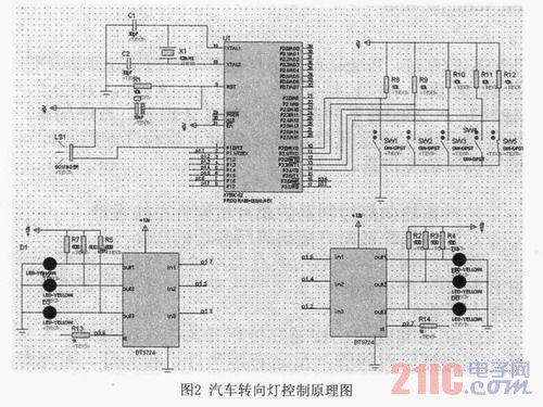
2.2.2 Car Steering Light Hardware Schematic 51 The single-chip microcomputer has a simple structure, low price and wide application. Therefore, the system uses AT89C5 1 MCU as the microcontroller. The input signal is connected to the P3 port of the single-chip microcomputer by a push button switch. When a person presses a certain switch, the control command is transmitted to the single-chip microcomputer, thereby driving the corresponding light group to work. The output signal lights are replaced by LEDs in Proteus, which are controlled and detected by the intelligent power switch BTS724. The BTS724 is a 4-channel, low on-resistance high-side switch with an integrated charge pump, CMOS-compatible, TTL-level, and status feedback for controlling various marker lights. The BTS724 has four channels of input and output, and each pair of input and output is independent of each other. The diagnostic feedback of the digital output can detect the open circuit fault in the OFF state (in the state where the light is not turned on), in the ON state (referring to the car) When the lamp is on, the feedback is overheated and turned off. For digital output type diagnostics, an open-circuit fault can be detected with the load off by adding an external pull-up resistor to the output. When the emergency switch is pressed, not only the 6 identification lights flashed, but also the alarms should be ringed at the same time to enhance the tension and drive the passers-by to avoid the car. The bell is replaced by a sounder in the Proteus, which makes a drip sound. According to the above analysis, the components are taken out from the component library and placed in the drawing area. The component properties are set according to the requirements, and then the wiring is completed to complete the drawing of the electrical schematic. For components that are not in the base library, you can make them yourself. You can also add libraries. Figure 2 is a schematic diagram of the control of the car turn signal.

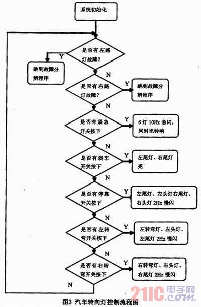
3 car turn signal software design Car turn signal controller is actually based on the state information of the lights and the driver's requirements for the state of the lights. The status information of the lights is mainly the feedback of the fault information, and the driver's request for the state of the lights is achieved by pressing different switches. The specific control idea is as follows: After the system is started and initialized, the timer is started and the lights controlled by the BTS724 are periodically detected, and the light switch is periodically scanned, and the light is determined according to the diagnosis result and the light switch. How does the group show and work? When a fault occurs, jump to the corresponding fault resolution procedure. In the fault resolution program, distinguish the cause of the fault and turn to the specific processing. At the same time, the five switches are cyclically scanned. When the emergency switch is pressed, the left turn light, the left headlight, the left taillight, the right turn light, the right headlight and the right taillight flash simultaneously, and the blinking frequency is 10 Hz; When the brake switch is pressed, the left taillight and the right taillight are simultaneously illuminated; when the docking station switch is pressed, the left headlight, the right headlight, the left taillight and the right taillight flash simultaneously, the blinking frequency is 2 Hz; when the left turn switch is turned on, The left turn light, the left headlight, and the left tail light flash simultaneously; the right turn switch is turned on, and the right turn light, the right head light, and the right tail light flash simultaneously, and the blinking frequency is 2 Hz.
The specific flow chart of the car turn signal control is shown in Figure 3.

The MCU simulation software Proteus can be jointly developed and simulated with KEIL software. After simple setup, open the schematic and KEIL program in Proteus, start debugging Debug-start/stop Debugsession in KEIL, and run Debug-go. At this time, Proteus hardware The simulation can be initiated by KEIL.
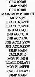
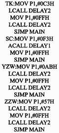
Some key procedures: 

4 Conclusion This article car steering light controller mainly realizes the electronic control of 6 lights, through the controller can achieve the control display of each car light, such as emergency, 6 lights flashing bells, turn left The lamp work flashes, etc.; the fault feedback can also be realized by the power switching device BTS724, so that the fault diagnosis of each lamp can be realized, so that the driver can clearly know the state of the lamp group of the vehicle, and take measures to prevent the bright light from appearing. The dangerous state of flashing does not flash, so as to remind the passing person's driving intention, greatly improving the safety of driving.
Wuxi Juxingyao Trading Co., Ltd , https://www.juxingyao.com