Abstract: When using the upper computer and Siemens s7300 series PLC to achieve automatic process control, when selecting MPI protocol for communication, the PLC can be programmed without programming, and it can read and write all data areas quickly and easily. However, Siemens did not publish the format of the MPI protocol. If users want to monitor using the MPI protocol, they must purchase their monitoring products or third-party manufacturers' configuration software. This brings certain difficulties to the user's own development. In particular, self-developed field devices cannot access the PLC through the MPI protocol. The use of other communication methods also has complicated programming and requires the purchase of software and authorization limitations. This paper through the data monitoring, acquisition, analysis method, parsed the key message format of the MPI protocol, can be used to achieve communication between the host computer, field devices and the CPU supporting the MPI protocol, thus providing a high efficiency and low cost way of communication.
Foreword
The modernization of industry is largely reflected in the automation of industrial production processes. The transmission of information and the exchange of data have become the criteria for evaluating the level of industrial automation. The diversification of network communication methods and the rapid increase in the speed of communication have enabled the information exchange field to extend from the equipment control layer to corporate management. The rapid development of information technology has promoted the transformation of the structure of automation systems. Distributed control systems based on networks have become the mainstream trend of today's automation systems. Therefore, the real-time and reliability of network communication, as well as the diagnosis and elimination of network faults have become the focus of industrial network communications. The MPI network is a communication method often used in Siemens industrial control systems and uses RS485 physical interfaces for data transmission. The following mainly describes the analytical method of the Siemens MPI protocol and the key message format.
MPI Protocol Overview
The MPI protocol has its full English name Multi-point-Interface. Between PLC can be configured as master/master protocol or master/slave protocol. How to operate depends on the device type: If the control stations are all s7-300/400 series PLC, then establish the master/master connection, because MPI protocol supports multi-master communication, all s7-300 CPU can be configured as network master Through the master/master protocol, data exchange between PLCs can be realized. If some control stations are s7-200 series PLCs, you can establish a master/slave connection because the s7-200 CPU is a slave. Users can use the network commands to read and write data from the s7-300 CPU to the s7200 CPU.
analysis of idea
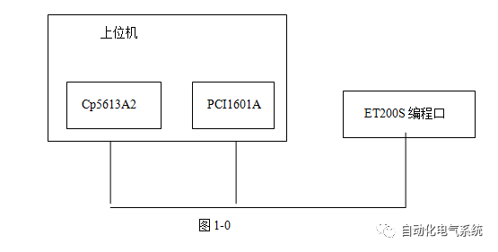
Siemens Step 7 V5.4 software is a development tool for S7-300 series PLCs (including ET200S). The host computer is connected to the programming port of the PLC through the communication interface (CP5613A2) on the PCI slot and the communication cable, and the communication card interface. PLC programming port is the RS485 interface standard. This shows that the PC can actually communicate with the ET200 CPU (IM151-7) through the RS485 serial port, but we do not know the communication protocol. Therefore, when using the PRODAVE S7 software provided by Siemens on the host computer to read and write the PLC, by monitoring the data on the communication port, we may be able to analyze the format of the communication message. Then, remove the Siemens communication card and send the message to the PLC directly through the RS485 serial port to verify its correctness and perform further operations. With this in mind, use the following steps to obtain these messages.
step
Hardware and software requirements
Hardware: serial port splitter and communication cable, Siemens CP5613A2 communication card, ADVANTECH PCI-1601A communication card, Siemens ET200S (IM151-7 CPU and related modules).
Software: step7 v5.4, simatic net 2006edition, prodave s7, serial portmonitor, PCI1601A driver, visualc++.
Hardware connection as shown in Figure 1-0

After installing relevant software and drivers, hardware testing and software platform construction
(1) Connection of serial port splitter and communication cable (Appendix A)
(2) Configuring ET200S with STEP 7 V5.4 and related initialization settings (Appendix B)
(3) Test of PCI1601A Communication Card (Appendix C)
(4) Serial port monitoring software setting and testing (Appendix D)
(5) PRODAVES7 Commissioning Operation (Appendix E)
After completing the setup and debugging, open the serial port monitoring software, and power on the PLC, run PRODAVES7 and start data monitoring when various operations (load, unload, read, write, etc.) are performed in it. Through comparative analysis, it is found that:
(1) Unlike the S7-200, regardless of the state (run or stop), the ET200S continuously sends out data to find devices once it is powered on, and continues to read and write data.
(2) A series of regular data is detected when connecting, reading, writing, and disconnecting. After multiple monitoring and comparison analysis, the data frame format of the relevant operation can be obtained. The addresses of the PLC and the host computer are initialized to be 02 and 00 respectively; for the convenience of description, the following symbol conventions are now made for the data frame format.
SD: (Start Delimiter) Start Delimiter
LE: (Length) message length
LER: (Repeated Length) Repeated Data Length
SD: (StartDelimiter) Start Delimiter
DA: (DestinationAddress) Destination Address
SA: (Source Address) source address
FC: Function Code Function Code
DSAP: (DestinationService Access Point) destination service access point
SSAP: (Source ServiceAccess Point) source service access point
FS: (Frame Sequence) frame sequence number
UU: (unkown unit) unknown operation unit, its value is usually a fixed value
GU:(group unit) grouping unit
DU: (Data Unit) data unit
FCS: (Frame CheckSequence) checksum
END: (End Delimiter) end delimiter
Analysis results
The load process
(1) Device search
After the PLC (ET200S) is powered on and enters the run state, it continuously sends out data to find the device. The data frame format is as follows. The DA has a total of 32 station numbers from 00 to 1F. Token frames and bus access frames are issued alternately in strict frame timing (15 frames/s).
Token Frame: DC DA SA
DC DA 02
Bus Access Frame: SD DA SA FC FCS END
10 DA 02 49 FCS 16
After running the Load command in prodave s7, the host computer also started sending data to find the device. The data frame format is as follows. The DA has a total of 32 station numbers from 00 to 1F. Token frames and bus access frames are issued alternately in strict frame timing (19 frames/s).
Token Frame: DC DA SA
DC DA 00
Bus Access Frame: SD DA SA FC FCS END
10 DA 00 49 FCS 16
SD, DC, FC, and END each occupy a byte length, which is a fixed value equal to 10, DC 49, 16, and FCS uses a sum check, equal to DA+SA+FC.
(2) Handshaking
After the host computer receives the token frame (dc 02 02) sent by et200s, it responds with its token frame (dc 00 00) and waits for et200s to reply. If it receives dc 00 02, the PC immediately returns dc 02 00. Handshake succeeded. The bus access handshake is consistent with the token handshake. During the read and write operations, the handshake is not interrupted.

Read operation
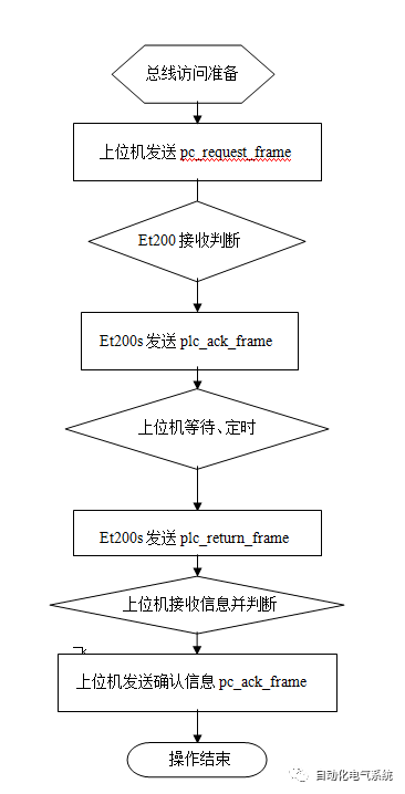
The steps of a read operation include the host computer issuing a read command frame (pc_request_frame_read), the PLC makes a correct response, and returns a confirmation information frame (plc_ack_frame_read) to the upper computer, and then feeds back a correct data information frame (plc_return_frame_read) to the upper computer. The host computer receives this frame data, and after the verification is confirmed, it makes a confirmation information frame (pc_ack_frame_read) to the PLC, thus completing a process of reading the data. During the read operation, the host computer and the PLC perform two responses in total.
Read command
The format of the request frame of the host computer when reading data is as follows. The frame occupies 38 bytes in length and is denoted as pc_request_frame_read(38).

SD LE LER SD occupies 4 bytes in length and is a fixed value.
Pc_request_frame_read(0)=68
Pc_request_frame_read(1) = 1F, frame length check, is the number of bytes of DA+SA+FC+DSAP+SSAP+FS+GU+DU.
Pc_request_frame_read(2)=1F Repeat frame length, same as the frame length check notation.
Pc_request_frame_read(3)=68
DA SA FC DSAP SSAP FS each occupy 7 bytes.
Pc_request_frame_read(4)=82 is numerically equal to the target station address plus 80
Pc_request_frame_read(5)=80 is numerically equal to the source station address plus 80
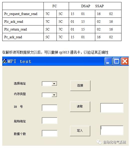
Pc_request_frame_read(6)=5C, 7C
Pc_request_frame_read(7)=16,15
Pc_request_frame_read(8)=02,01
Pc_request_frame_read(9)=F1 is the delimiter and its value does not change.
Pc_request_frame_read(10)=00~FF, frame number, self-enumeration for the same operation. When answering a handshake, it is used to determine if the current reply frame is a reply to this request.
UU occupies 6 bytes in length and is a fixed value
Pc_request_frame_read(11)=32
Pc_request_frame_read(12)=01
Pc_request_frame_read(13)=00
Pc_request_frame_read(14)=00
Pc_request_frame_read(15) =33
Pc_request_frame_read(16)=02,01
GU occupies 6 bytes in length and can be manipulated while reading and writing
Pc_request_frame_read(17)=00
Pc_request_frame_read(18)=0E
Pc_request_frame_read(19)=00
Pc_request_frame_read(20)=00
Pc_request_frame_read(21)=04
Pc_request_frame_read(22)
Single read and write pc_request_frame_read (22) = 01, the other does not change;
Mixed read and write pc_request_frame_read (22) for other values.
The DU unit occupies 12 bytes in length from pc_request_frame_read(23) to pc_request_frame_read(26). The 4 bytes are fixed values.
Pc_request_frame_read(23)=12
Pc_request_frame_read(24)=0A
Pc_request_frame_read(25)=10
Pc_request_frame_read(26)=02
The two bytes of pc_request_frame_read(27) and pc_request_frame_read(28) together indicate the number of data read. When the read memory area is I, Q, M, DB, it represents the number of bytes when the memory area is C, T. Indicates the number of counters or timers read.
If you read two bytes, it is:
Pc_request_frame_read(27)=00
Pc_request_frame_read(28)=02
If you read a counter or timer, it is:
Pc_request_frame_read(27)=00
Pc_request_frame_read(28)=01
Pc_request_frame_read(29) and pc_request_frame_read(30) collectively indicate the DB number to be operated. If other areas are read, both are 00 00.
Pc_request_frame_read(31) indicates the storage area type. For details, refer to Table 1-1.

Pc_request_frame_read(32)
Pc_request_frame_read(33)
Pc_request_frame_read(34) indicates the start address of the operation. The I, Q, M, and DB memory areas are calculated according to bits, and the C and T memory areas are calculated according to the number of bits.
If you read DB1B1, it will be
Pc_request_frame_read(32)=00
Pc_request_frame_read(33)=00
Pc_request_frame_read(34)=08
If you read C1 or T1,
Pc_request_frame_read(32)=00
Pc_request_frame_read(33)=00
Pc_request_frame_read(34)=01
Pc_request_frame_read(35) is the frame check code, and uses the sum-estimation algorithm:
(DA+SA+FC+DSAP+SSAP+FC+UU+GU+DU ) mod 16#100
Pc_request_frame_read(36), pc_request_frame_read(37) are terminators, and are fixed values, which are respectively equal to 16 E5.
When the PLC receives the request command (pc_request_frame_read), it returns a data frame to indicate the response after confirmation, occupies 15 bytes in length and is denoted as plc_ack_frame_read(15). The format is as follows:

SD LE LER SD
Plc_ack_frame_read(0)=68
Plc_ack_frame_read(1)=08
Plc_ack_frame_read(2)=08
Plc_ack_frame_read(3)=68
DA, SA
Plc_ack_frame_read(4)=80
Plc_ack_frame_read(5)=82
FC
Plc_ack_frame_read(6)=7C 5C
DSAP, SSAP
Plc_ack_frame_read(7)=02
Plc_ack_frame_read(8)=16
UU
Plc_ack_frame_read(9)=B0
Plc_ack_frame_read(10)=01
FS
Plc_ack_frame_read(11)
Frame number, consistent with pc_request_frame_read(10).
FCS
Plc_ack_frame_read(12)
Frame check, equal to (DA+SA+FC+DSSAP+SSAP+UU+FS+FCS)mod 16#100
END
Plc_ack_frame_read(13)=16
Plc_ack_frame_read(14)=E5
After sending the response data frame (plc_ack_frame_read), the PLC then feeds back to the host computer the data information frame (plc_return_frame_read) to be read, the length of which varies depending on the number of read bytes, and the format is as follows:

SD LE LER SD
Plc_return_frame_read(0)=68
Plc_return_frame_read(1)
Plc_return_frame_read(2)
Plc_return_frame_read(3)=68
DA SA FC DSAP SSAP FS each one byte
Plc_return_frame_read(4)=80
Plc_return_frame_read(5)=82
Plc_return_frame_read(6)=5C
Plc_return_frame_read(7)=16
Plc_return_frame_read(8)=02
Plc_return_frame_read(9) Delimiter, fixed value F1
Plc_return_frame_read(10), consistent with plc_ack_frame(11).
UU occupies 8 bytes in length and is a fixed value
Plc_return_frame_read(11)=32
Plc_return_frame_read(12)=03
Plc_return_frame_read(13)=00
Plc_return_frame_read(14)=00
Plc_return_frame_read(15)=33
Plc_return_frame_read(16)=02
Plc_return_frame_read(17)=00
Plc_return_frame_read(18)=02
GU occupies 6 bytes in length
Plc_return_frame_read(19)=00
Plc_return_frame_read(20)
Equal to the number of reads plus 4, if a byte is read 05
Plc_return_frame_read(21)=00
Plc_return_frame_read(22)=00
Plc_return_frame_read(23)=04
Plc_return_frame_read(24)
01 for single read, other values ​​for packet read.
DU occupy (4+pc_request_frame_read(27)+pc_request_frame_read(28)) byte length
Plc_return_frame_read(25)=FF
Plc_return_frame_read(26)=04
Plc_return_frame_read(27), plc_return_frame_read(28) collectively indicate that the number of bits of data read is returned, calculated according to bits; if one byte is read, then they are 00, 08 respectively.
The PLC returns the data to be read, and sequentially stores them from the low address to the high address.
Plc_return_frame_read(29)
Plc_return_frame_read(30)
.
.
Plc_return_frame_read(n)
n=28+ bytes read
Plc_return_frame_read(n+1) is FCS, and the remainder check is used.
END
Plc_return_frame_read(n+2)=16
Plc_return_frame_read(n+3)=E5
After receiving the data, the upper computer sends a confirmation frame (pc_ack_frame_read) to the PLC for a total length of 15 bytes, which is denoted as pc_ack_frame_read(15).
The format is as follows:

SD LE LER SD
Pc_ack_frame_read(0)=68
Pc_ack_frame_read(1)=08
Pc_ack_frame_read(2)=08
Pc_ack_frame_read(3)=68
DA SA
Pc_ack_frame_read(4)=82
Pc_ack_frame_read(5)=80
FC
Pc_ack_frame_read(6)=5C
DSAP SSAP
Pc_ack_frame_read(7)=16
Pc_ack_frame_read(8)=02
UU
Pc_ack_frame_read(9)=B0
Pc_ack_frame_read(10)=07
FS
Pc_ack_frame_read(11) is consistent with plc_return_frame(10)
FCS
Pc_ack_frame_read(12)
Using the sum check algorithm, equal to (DA+SA+FC+DSSAP+SSAP+UU+FS)mod 16#100
END
Pc_ack_frame_read(13)=16
Pc_ack_frame_read(14)=E5
Read data process is completed.
Write operation
A complete write operation step includes: first, the host computer issues a write command information frame (pc_request_frame_write), and the PLC receives the judgment later. If it is correct, it responds and returns the confirmation information (plc_ack_frame_write) frame to the host computer and feeds it back. The correct data (plc_return_frame_write) frame is sent to the host computer. The host computer receives this frame data, and after the verification is correct, it makes a confirmation message to the PLC (pc_ack_frame_write), thus completing a process of reading the data. During the read operation, the host computer and the PLC perform two responses in total.
The length of the byte occupied by the upper computer request frame (pc_request_frame_write) at the time of writing is indefinite, and is related to the number of data to be written. Remember as pc_request_frame_write() with the following format:

SD LE LER SD
Pc_request_frame_write(0)=68
Pc_request_frame_write(1) pc_request_frame_write(2) 24 when writing one byte, 25 when writing two bytes...
Pc_request_frame_write(3)=68
DA SA FC DSAP SSAP FS
Pc_request_frame_write(4)=82
Pc_request_frame_write(5)=80
Pc_request_frame_write(6)=5C
Pc_request_frame_write(7)=16
Pc_request_frame_write(8)=02
Pc_request_frame_write(9)=F1
Pc_request_frame_write(10) is the frame number from 00 to FF
UU occupies 6 bytes in length
Pc_request_frame_write(11)= 32
Pc_request_frame_write(12)=01
Pc_request_frame_write(13)=00
Pc_request_frame_write(14)=00
Pc_request_frame_write(15)=43
Pc_request_frame_write(16)=02
GU occupies 6 bytes in length
Pc_request_frame_write(17)=00
Pc_request_frame_write(18)=0E
Pc_request_frame_write(19) and pc_request_frame_write(20) together indicate the number of bytes written plus 4. If you want to write 2 bytes, then 00, 06.
Pc_request_frame_write(21)=05
Pc_request_frame_write(22)=01
The length occupied by the DU is related to the number of bytes to be written, and its length is
(16+ pc_request_frame_write(21)+pc_request_frame_write(22)- 4) bytes, the reset operation is calculated as one byte.
Pc_request_frame_write(23)=12
Pc_request_frame_write(24)=0A
Pc_request_frame_write(25)=10
Pc_request_frame_write(26) is related to memory area. When writing C area, it is 1C, M area reset is 01, and other memory area is 02
Pc_request_frame_write(27)=00
Pc_request_frame_write(28)=01
Pc_request_frame_write(29) and pc_request_frame_write(30) collectively indicate the DB number to be written, and when writing other storage areas, it is 00 00. Note that the I and T areas cannot be written.
Pc_request_frame_write(31) indicates the type of memory area, refer to Table 1-2

Pc_request_frame_write(32)
Pc_request_frame_write(33)
Pc_request_frame_write(34)
The above three bytes indicate the starting address to be written. For the C area, it is the starting counter number, and if it is written to C2, it is 00 00 02 in sequence. When writing to other areas, it indicates the start bit address. If you want to write DB1B1, it is 00, 00, and 08 in order.
Pc_request_frame_write(35) and pc_request_frame_write(36) are related to the storage area. When writing to the C area, the sequence is 00 09. When the reset operation is performed, the sequence is 00 03. Writing to other areas (including writing bytes to the M area) is 00,04.
Pc_request_frame_write(37) and pc_request_frame_write(38) collectively indicate the amount of data to be written, depending on the type of memory area. Write C area when the number of bytes written, for example, a counter write operation, the value is 00,02 in order; write other memory area when the number of data to be written, according to the bit calculation, if written DB1B0, then 00,08.
Pc_request_frame_write(39)
Pc_request_frame_write(40)
Pc_request_frame_write(41)
.
.
Pc_request_frame_write(n)
The above several bytes represent the data to be written, and they are arranged in the order from low address to high address. When writing to the C area, the data is represented as a BCD code, and when writing to other memory areas, the data are all sixteen. Binary format representation.
n=38+ pc_request_frame_write(19)+pc_request_frame_write(20)- 4).
Pc_request_frame_write(n+1) is FCS, using the summation and the remainder algorithm, equal to
(DA+SA+FC+DSAP+SSAP+FS+UU+GU+DU)mod 16#100
END
Pc_request_frame_write(n+2)=16
Pc_request_frame_write(n+3)=E5
After receiving the request data frame confirmation, the PLC returns a confirmation information frame (plc_ack_frame_write)
Occupy 15 bytes in length, the format is as follows:

SD LE LER SD
Plc_ack_frame_write(0)=68
Plc_ack_frame_write(1)=08
Plc_ack_frame_write(2)=08
Plc_ack_frame_write(3)=68
DA SA FC DSAP SSAP
Plc_ack_frame_write(4)=80
Plc_ack_frame_write(5)=82
Plc_ack_frame_write(6)=5C
Plc_ack_frame_write(7)=02
Plc_ack_frame_write(8)=16
UU
Plc_ack_frame_write(9)=B0
Plc_ack_frame_write(10)=01
FS
Plc_ack_frame_write(11) is consistent with pc_request_frame_write(10).
FCS
Plc_ack_frame_write(12) uses the sum check algorithm.
END
Plc_ack_frame_write(13)=16
Plc_ack_frame_write(14)=E5
Plc_return_frame_write frame format

Remember as plc_return_frame_write(29)
SD LE LER SD
Plc_return_frame_write(0)=68
Plc_return_frame_write(1)=16
Plc_return_frame_write(2)=16
Plc_return_frame_write(3)=68
DA SA FC DSAP SSAP FS
Plc_return_frame_write(4)=80
Plc_return_frame_write(5)=82
Plc_return_frame_write(6)=7C
Plc_return_frame_write(7)=02
Plc_return_frame_write(8)=16
Plc_return_frame_write(9)=F1
Plc_return_frame_write(10), FS, is consistent with plc_ack_frame_write(11).
UU occupies 15 bytes in length
Plc_return_frame_write(11)=32
Plc_return_frame_write(12)=03
Plc_return_frame_write(13)=00
Plc_return_frame_write(14)=00
Plc_return_frame_write(15)=43
Plc_return_frame_write(16), consistent with pc_request_frame_write(16).
Plc_return_frame_write(17)=00
Plc_return_frame_write(18)=02
Plc_return_frame_write(19)=00
Plc_return_frame_write(20)=01
Plc_return_frame_write(21)=00
Plc_return_frame_write(22)=00
Plc_return_frame_write(23)=05
Plc_return_frame_write(24)=01
Plc_return_frame_write(25)=FF
FCS
Plc_return_frame_write(26) uses the sum check algorithm.
END
Plc_return_frame_write(27)=16
Plc_return_frame_write(28)=E5
Pc_ack_frame_write frame format

Remember as pc_ack_frame_write(15)
SD LE LER SD
Pc_ack_frame_write(0)=68
Pc_ack_frame_write(1)=08
Pc_ack_frame_write(2)=08
Pc_ack_frame_write(3)=68
DA SA FC DSAP SSAP
Pc_ack_frame_write(4)=82
Pc_ack_frame_write(5)=80
Pc_ack_frame_write(6)=7C
Pc_ack_frame_write(7)=16
Pc_ack_frame_write(8)=02
UU
Pc_ack_frame_write(9)=B0
Pc_ack_frame_write(10)=07
FS
Pc_ack_frame_write(11) plc_return_frame_write(29) remains consistent.
FCS
Pc_ack_frame_write(12) uses a sum check algorithm.
END
Pc_ack_frame_write(13)=16
Pc_ack_frame_write(14)=E5
The write data process is complete.
For reading and writing data frame FC and DSAP and SSAP do

Test source code in Appendix F.
Conclusion
This article uses the serial port monitoring method to parse out the message format of siemens MPI protocol through simple and easy operation. The result has great use value. (1) The user can make the host computer without using Siemens dedicated communication processing card. The PLC communicates to achieve the required control functions and saves costs. (2) Reduced the difficulty of user self-development, making communication programming simple and straightforward. Without purchasing software and authorization, you can use the MPI protocol to monitor the working status of the PLC.
Cummins ≥1000KW Diesel Generator
Cummins ≥1000Kw Diesel Generator,Cummins Open Diesel Generator,Canopy Type Diesel Generator,Cummins Power Generator Set
Shanghai Kosta Electric Co., Ltd. , https://www.generatorksd.com