As one of the bioelectrical signals, the myoelectric signal is the root of the electrical signal that produces muscle power. It is the superposition of the action potentials of many motor units in time and space, which largely reflects the movement of nerves and muscles. status. From the point of view of the source of the myoelectric signal, there are generally two kinds, one is obtained by inserting the needle electrode into the muscle, that is, the needle type myoelectric signal, which has the advantages of small interference and easy identification, but causes harm to the human body; The electromyographic signal of the surface of the human skin, that is, the surface electromyography signal (sEMG), is obtained through the electrode sheet. This method is relatively simple and has no harm to the human body, and is commonly used. The surface EMG signal is collected in this design.
Surface EMG signals can be obtained from many parts of the body, such as calves, thighs, waist, back, neck, etc. The surface EMG signals obtained from different parts carry the movement and function information of the corresponding parts. For example, the myoelectric signal on the leg reflects the state of motion of the leg, such as walking, running, underarm, and the like. It is of great value to use surface EMG signals to study the state of motion of the human body. In medical rehabilitation projects, surface EMG signals can be used for patient treatment. In bionics, surface EMG signals can be used for artificial prosthetic research.
Second, the overall design of the program
Figure 1 Scheme system block diagram
As can be seen from the above design block diagram, the system design is mainly composed of five parts, of which filtering and amplification are the main part of the circuit design, because the work behind the surface EMG signal will not be possible. The signal conversion is mainly for A/D conversion work, and the signal representation is to draw the surface EMG.
Third, the program hardware design
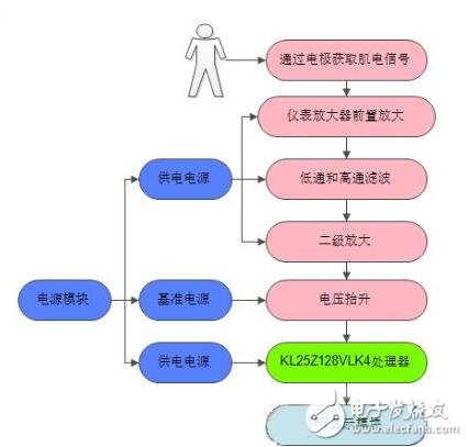
Figure 2 System hardware part design block diagram
The hardware design part is mainly four modules: analog signal module, microprocessor module, TFT display module and power module. The above figure has been marked with different colors.
Camera Module is generally composed of the following parts: Lens, image sensor, base bar and line.
If it is a camera module with AF function (generally a mobile phone camera), most of them adopt VCM mode, which has one more coil than the above structure. By adding points to the coil, the lens can move vertically to achieve the function of focusing. In the case of a camera with a shake resistant feature, the lens is also able to move horizontally to achieve an optical shake resistant effect
Camera module selection
The sensor and lens in the camera module usually account for more than 90% of the cost, and the image quality is also determined by them.
First, choose the most appropriate sensor according to the price you can accept, the interface of the motherboard, and the resolution you need to take photos and video
The price of the sensor usually accounts for 40%-60% of the price of the module. In order to ensure that the resolution/frame rate can meet the requirements, sensors with better sensitivity and larger pixel area are selected at a certain cost.
Secondly, according to the purpose of the sensor you need, choose the lens with the appropriate size and field of view Angle. If a lens with a large field of view is needed, you can choose a fish-eye camera (also known as a wide-angle camera). However, for the image taken by the fisheye camera, there will be a distortion effect. In fact, the distortion effect can be corrected by itself.
Elp Usb Camera,Laptop Camera Module,Blink Sync Module Usb Port,Phone Camera Module To Usb
Shenzhen Zhenniu Technology Co., Ltd , https://www.tydisplay.com