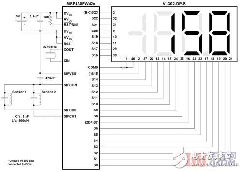
Resonant LC Sensor technology has been used for motion detection for several years, including flow metering and other low-speed rotation detection systems. In almost all cases, the common mainstay driving the development of these sensor designs is the need for low-power solutions, which are typically low-power solutions for battery-powered devices. Combining the analog measurement component with the state machine processing interface independent of the main CPU operation, this article takes Texas Instruments' MSP430FW42x series 16-bit MCU as an example to give a clear explanation of the ultra-low power motion detection system solution. Figure 1 shows the implementation of a simple rotary motion detection system. In addition to the microcontroller and display, the configuration of the two-channel resonant LC sensor is shown. A single sensor can only be used for rotation detection, and a second sensor can be added to provide direction information.

Figure 1 Schematic diagram of the MSP430FW42x rotating system
Sensor principle
The basic principle of using a resonant LC sensor is related to the magnetic field interference radiated by the inductor when the LC circuit oscillates. The above oscillation is caused by the LC sensor pulse, and then one side is released as a high impedance. The oscillating frequency after excitation is the fundamental frequency of the sensor and is calculated as follows:

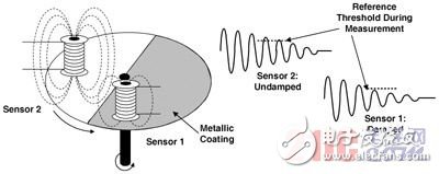
Once the circuit enters the oscillation, the LC fOSC output quickly decays to zero with the stored energy consumption. When oscillating, the current through the sensor generates a magnetic field that is usually unaffected by external factors. But when there is a metal surface close to the oscillating inductor, the signal decay rate will be much faster. Figure 2 shows a more detailed view of the sensor configuration and shows the damping wheel and the corresponding output signal.

Figure 2 Sensor configuration and oscillation
As shown in Figure 2, sensor 1 is affected by the metal coating portion of the rotating wheel. The oscillation attenuation rate is increased compared to the signal output of the unaffected sensor 2. The induced eddy current formed by the magnetic field cutting on the metal surface increases the load on the LC sensor, thereby accelerating the storage energy consumption of the excitation oscillation. The increased decay rate can also be referred to as the sensor attenuation produced by the metal surface. If the attenuation signal corresponding to the corresponding un-attenuated condition can be successfully detected, the system that can detect the carefully designed rotating wheel provides a means of sensing the motion of a given system.
Detection circuit
The excitation of each sensor is provided by a simple pulse on one side of the sensor. Oscillation detection and more important changes in attenuation rate detection are implemented with simple comparators and voltage references. We use an oscillating signal to drive one input of the comparator and a reference signal to drive the other input. Thus, if the comparator output is greater than the reference voltage, it will oscillate with the sensor output; if the oscillation is lower than the comparator reference voltage, the comparator output Will become zero. By blocking the comparator output, the transition from the analog sensor system to the digital domain is completed and uC processing is possible. If we carefully calibrate the drop between the comparator reference and the attenuation and un-attenuation oscillations at the specific point of the signal, the comparator output will reflect the state of the sensor. If we replace the reference with a general-purpose digital-to-analog converter (DAC), then it is easy to calibrate the reference voltage and actively modify the reference voltage according to the requirements of the slightly different sensor of the system, or apply hysteresis to the measurement system.
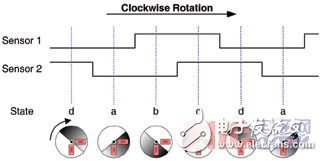
For the detailed system shown in Figure 1, we use a dual sensor setup to detect both rotation and direction. If we place the sensor 90 degrees apart and use a 180 degree metal coated wheel as shown in Figure 2, the dual LC sensor produces a quadrature signal that provides a rotational and direction encoded signal. Figure 3 shows the sensor changes as the wheel turns and the corresponding digital decoding.

Figure 3 Dual LC sensor quadrature digital output
While it is relatively simple to detect attenuated and un-attenuated sensor outputs and convert them to digital outputs, it is quite difficult to process the above data and apply it to a larger state machine. The host controller must not only mobilize and measure the sensors in the system, but must also take action when the rotation is detected and track the direction and processing of the sensor information. As mentioned above, we can achieve this with additional discrete solutions, and the integration of digital and analog components required gives us the potential to implement lower cost, lower power solutions.
The combination and integration of the analog and digital processing components we refer to here forms the basis of ultra-low-power microcontrollers, especially for applications using the above sensor configurations. Scan Interface (SIF) The building blocks required to scan each sensor and process digital data are integrated into a single hardware module that the system designer can fully program.
Since LC sensors only generate power in short excitation pulses, these sensors are ideal for applications where each part of the micro-amplifier affects the overall system success or failure. When combined with an ultra-low power architecture, the overall system's low power consumption can be achieved.
System summary
Figure 1 shows the detailed system operation with an average current consumption of just under 4uA. The total system current consists of continuous excitation and measurement of each sensor, CPU wake-up for data processing after each full rotation, and LCD display based on static segments. When using a typical battery-powered solution such as the 220mAHr 3V CR2032, the life of a similar system can be more than 5 years, calculated as follows:

The average time current consumption for sensor excitation and measurement is approximately 2.7uA, while the additional LCD current is approximately 1uA. Simple changes such as increasing the minimum number of revolutions or reducing the LC sensor excitation frequency before CPU data processing can further reduce the system's average current consumption, thereby extending the life of a single-cell powered system.
The industry has used resonant LC sensor technology for many years, and integrating this sensor interface with ultra-low-power processors opens the door to a new generation of smart sensing systems. The MSP430FW42x family of microcontrollers integrates all the features needed to meet critical system requirements such as high efficiency, small form factor, low cost, and faster time-to-market for a wide range of motion detection applications. The new MSP430FW42x family is not only suitable for ultra-low power systems, but the flexibility and power of SIF hardware modules also help to develop complex state machines and state machine processing, freeing the CPU from traditional tasks. This integration increases CPU efficiency, reduces system power consumption, and frees CPU bandwidth for other tasks such as data communication, more robust user interfaces, and more complex data processing.
CCTV Tester,Cctv Camera Tester,Monitor Tester,IP Camera Test Monitor
Chinasky Electronics Co., Ltd. , https://www.chinacctvproducts.com