In order to solve the problem that most home service robots do not have walking function or simply have obstacle avoidance ability, this paper designs a home service robot system based on STM32. The entire system consists of wheeled robots, XBee coordinator, RFID smart floor and host computer. The wheel robot consists of a main board, a sensor module, a radio frequency module, a servo module, a power supply module, and a robot metal body. The sensor module includes an electronic compass, an infrared sensor, and an RFID reader. The mainboard is developed with the ARM Cortex-M3 core microprocessor STM32F103VCT6 as its core, collecting sensor module data information and realizing the communication connection between the robot and the XBee coordinator. The system can accomplish the task of setting and stably and efficiently through autonomous decision making in the environment of a simulated smart home, and can meet the application requirements of the home service robot.
With the development of artificial intelligence and sensor technology, the robot has entered the people's daily life environment from the factory's structured environment. The robot can not only complete the work autonomously, but also work together with people to complete tasks or complete tasks under the guidance of people. Home service robots are an important part of the smart home system and play an increasingly important role in life. At present, most home service robots do not have walking functions or simply have obstacle avoidance capabilities. The research of robots depends heavily on simulation, but the actual situation and simulation results may be very different. There are also some studies that have complicated the issue and have taken more detours.
In view of the shortcomings of current home service robots and the requirements of modern intelligent service robots, this paper proposes a design scheme of home service robot system based on STM32. The program simulates the smart home environment, simplifies the positioning method, effectively uses the low-cost, low-power features of the ZigBee technology [3], designs a wheel robot of a suitable size to perform experiments, and the test results show that the robot can achieve the desired goal. And it shows strong self-determination ability.
1 overall system design
The entire home service robot system is mainly composed of four parts, including a simulated smart home environment covered with RFID smart floor, a mobile wheeled robot, an XBee coordinator, and an upper computer.
The smart home environment has a design length of 3.25 meters and a width of 2 meters. It is covered with an RFID smart floor and is divided into two rooms, a kitchen and a living room. The middle door is 0.3 meters wide. The kitchen has sinks, shelves, smart refrigerators and other appliances, the living room has a dining table, dining chairs and so on. The RFID smart floor arrangement information provides the robot with accurate positioning. Wheeled robots are responsible for transporting goods to and from the client between the kitchen and the living room, and are the core of the entire system. The XBee coordinator is a wireless transmission module based on ZigBee technology and is responsible for fast and stable data transmission. The host computer is mainly responsible for the data receiving, processing and the release of control instructions.
2 system working principle and process
The main workflow of the system is: the host computer enters the task command, and the command is sent to the wheeled robot through the XBee coordinator. After receiving the task command, the robot starts from the sleep mode, reads the RFID floor positioning information of the intelligent floor, and uploads the real-time position information to the upper computer to display the robot motion track. The robot detects its own posture and surrounding obstacles through the sensor module, autonomously decides to move to the target location to grab the item, and transports it to the final target location for use by the service object. Among them, wheeled robots are the focus of the entire system design.
2.1 XBee Coordinator Workflow
The XBee coordinator is the first XBee network node that is started. It mainly performs the networking functions and data sending and receiving functions of the XBee network. The networking functions include the establishment of the XBee network and the access of the sub-nodes.
First, the various modules including hardware and software are initialized after the XBee coordinator is powered-on reset. Then, start scanning channels, perform energy detection, select channels, and select the appropriate PAN ID. After the success, the network ID and channel are broadcasted, and the XBee network is established. After that, the XBee coordinator enters the listening state and waits for the child node to send a network access request signal. After receiving the network access request, the coordinator allows the child node to access the network and allocates the network short address to the child node. This implements the network access function of the node. Finally, the XBee coordinator sends the host computer data to the child node RF module, starts the wheeled robot, and after receiving the data request from the child node, the XBee coordinator will receive the data and transmit it to the host computer through the serial port line. This is the data sending and receiving function. .
2.2 Wheeled Robot Workflow
The wheeled robot is a task execution device that runs between the two rooms in the kitchen and the living room, performs various command tasks sent by the user object accurately and efficiently, and sends the robot coordinate data to the XBee coordinator for the following work.
First of all, the XBee module on the wheeled robot needs to initialize and send a request to enter the network to implement node access. Then, the XBee module receives task command data transmitted by the XBee coordinator, and the main board initializes each sensor module. The RFID reader reads the smart floor coordinate data and sends it to the XBee coordinator. The electronic compass acquires the current posture information of the robot. The infrared sensor detects the obstacle distance of the environment in which the robot is located, and the main board controls the start of a moving wheel composed of two left and right continuous steering servos. The robot autonomously makes decisions on the planned path, moves to the target position, and starts the robotic arm to grab items. The robotic arm is composed of multiple angle servos. With the robotic arm holding the object, the planned path is again moved to the final location, and the robotic arm accurately positions the object at the target position. After completing the task, the robot returns to the starting position and enters sleep mode.
3 key links design
3.1 Robot Hardware Structure Design
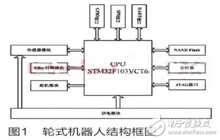
The wheeled robot adopts the modular design principle, which makes the robot's design a modular way and uses layered control, which is conducive to the comprehensive performance [4]. The robot system is divided into five parts: the main board, the sensor module, the radio frequency module, the steering gear module, and the power supply module. The block diagram of the wheeled robot is shown in Figure 1.
3.1.1 Motherboard
The motherboard is designed for this wheeled robot and uses an ARM Cortex-M3 core STM32F103VCT6 processor. The motherboard resources include SDRAM, NAND Flash, UART interface, GPIO interface, SPI interface, and JTAG interface. The auxiliary resources are USB interface, timers, etc.
The design of the main board provides interfaces for the RF module, sensor module, and robot arm module, which simplifies the circuit structure, makes the controller more integrated, and runs more stable and efficient, thereby saving hardware costs.
3.1.2 Sensor Module
The sensor module consists of sensors and corresponding signal conditioning circuits. Sensors used in wheeled robots include infrared sensors, electronic compasses and RFID readers. According to the accuracy requirement of detecting the obstacle distance during the movement of the wheeled robot, the model of the infrared sensor is Sharp GP2D12, which is installed at the front, left front, right front, left and right positions of the robot. The electronic compass adopts the HMC5883L three-axis electronic compass in the GY-80 nine-axis module, which can measure accurate azimuth values ​​in complex environments and has strong anti-magnetic and electrical interference capabilities. The RFID reader uses Parallax' low-band 28140 reader to read 125kHz tags.
3.1.3 RF Module
The RF module is the main module for communication between devices and is responsible for the data transmission of the entire network. The radio frequency module adopts the XBee wireless transmission module based on ZigBee technology. The module has a large coverage area and is easy to configure. It is a good choice for robot communication network.
The XBee coordinator consists of an XBee wireless module and an XBee USB adapter board. The XBee USB adapter board is specially designed for the XBee wireless module. By using this module, the XBee wireless module can be configured on the PC and the serial port communication monitoring can be performed using the X-CTU software. The XBee coordinator communicates with the host computer via a USB cable.
3.1.4 Servo Module
The servo module is divided into a mechanical arm servo and a moving wheel servo, and the mechanical arm is composed of an angle servo and a metal rod. The five-angle steering gear constitutes a five-degree-of-freedom robotic arm, and the size is matched with the construction of a smart home environment. In order to ensure the robot arm movement accuracy, the HS-322HD angle servo is adopted. The mobile wheel servo uses a Parallax continuous rotary servo.
3.1.5 Power Module
According to the different occasions and characteristics of the various components of the work, using different power modes, the wheeled robot uses a battery-powered mode, and the XBee coordinator must remain in working condition, so the use of USB power supply mode of the host computer. The power module is connected to the main board, and the main board has interfaces to the sensor module, the radio frequency module, and the servo module, and the sensor module, the radio frequency module, and the servo module are powered through the interface. Because of the high current requirements of RFID readers, the motherboard and RFID readers use dual power supplies separately.
3.2 Robot Software Design
3.2.1 Drive Control Design
The drive control design includes the initialization of each module, the communication between the modules, and the upper computer software design. This article adopts MDK-ARM with STM32F103VCT6 as the development environment and completes the initialization and communication of each module. The upper computer software is developed using VC++. The specific functions and workflows implemented by each module software have been introduced in the working principle and flow of the system and will not be described here.
3.2.2 Path Planning
Path planning can be mainly divided into global path planning and local path planning. The former means that the robot plans a collision-free optimal path from the initial position to the target position when the environmental information is completely known; the latter is unknown because the environmental information is unknown. , need to consider the specific circumstances of the local path adjustment.
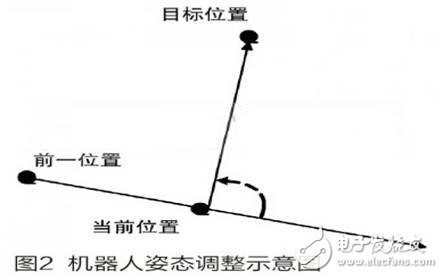
During the movement of the robot, an electronic compass is used to adjust the posture, that is, to adjust the direction of advancement and strive to find the quickest route to reach the target position. The robot attitude adjustment mainly depends on the distance between the current position and the previous position and the target position, including the horizontal distance and the vertical distance. If the horizontal and vertical distances between the current position and the target position are less than or equal to the horizontal distance and the vertical distance between the previous position and the target position, the distance between the robot and the target position gradually decreases, and the robot advances toward the target position. Otherwise, it indicates that The robot did not advance according to the expected trajectory and needed to make attitude adjustments again. The gesture adjustment diagram is shown in Figure 2.
Local path planning includes obstacle avoidance processing, oscillating position analysis, door position search, and door-door strategy analysis. During the movement of the robot, it is necessary to constantly detect the surrounding environment so as to better decide the next step. The five infrared sensor data allow the robot to grasp the surrounding environment at all times, and the obstacle avoidance processing requires the robot to reasonably avoid the obstacle and move to the target position.
The oscillating position means that the robot cannot pass a certain position smoothly, and repeatedly moves back and forth around this point. If the starting position and the target position are in two rooms respectively, under the guidance of the global path planning idea, the robot will continue to linger on the common walls of the two rooms. The schematic diagram of the oscillation position analysis is shown in Figure 3.
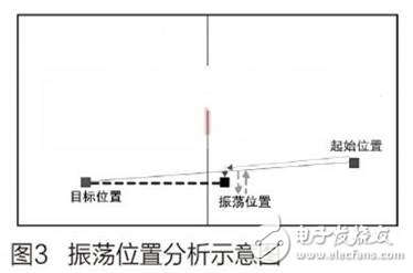
When the robot reaches the oscillating position, the path planning strategy needs to be adjusted. At this time, the global path planning strategy is abandoned and the public wall is used as the reference wall to search for the door. The basic rule for the algorithm to follow the wall is: When the robot is approaching the wall, it is necessary to adjust the two-wheel speed difference to make the robot move away from the wall; when the robot keeps away from the wall, it is necessary to adjust the speed difference between the two wheels to make the robot toward Go near the wall. The result of the comprehensive adjustment is that the forward trajectory of the robot is a quasi-sinusoid with the base line as the axis. The trajectory along the wall is shown in Figure 4.
Passing through the door is an indispensable part of the robot's mission. How to ensure that the robot passes through the door is the key to success. When the robot is preparing the door, it is not facing the door and may be tilted to the left or right. According to the division of the degree of tilt, the robot detects the distance value of the corresponding infrared sensor, and constantly adjusts the robot's attitude so that the robot is facing the door and passes smoothly.

4 Conclusion
The home service robot system designed in this paper proposes detailed and feasible solutions for the tasks of smart home environment service objects. The entire system has applied the mainstream wireless communication technology based on the XBee module to ensure the data transmission rate. In addition, the modular design of the wheeled robot has the characteristics of simple structure and stable performance, which greatly improves the reliability of the home service robot and reduces the hardware cost of the system. Path planning in autonomous decision making allows the robot to quickly move along the most suitable route. In short, the design system provides a reference for solving problems related to home service robots.
AURORA SERIES DISPOSABLE VAPE PEN
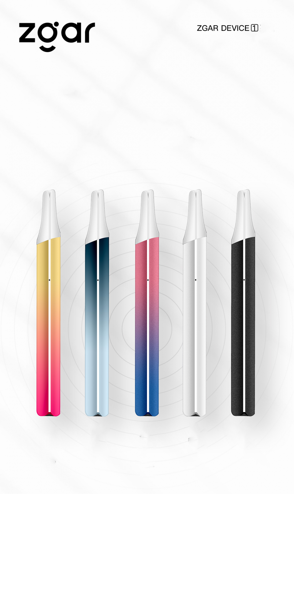
Zgar 2021's latest electronic cigarette Aurora series uses high-tech temperature control, food grade disposable pod device and high-quality material.Compared with the old model, The smoke of the Aurora series is more delicate and the taste is more realistic ,bigger battery capacity and longer battery life. And it's smaller and more exquisite. A new design of gradient our disposable vape is impressive. We equipped with breathing lights in the vape pen and pod, you will become the most eye-catching person in the party with our atomizer device vape.The 2021 Aurora series has upgraded the magnetic suction connection, plug and use. We also upgrade to type-C interface for charging faster. We have developed various flavors for Aurora series, Aurora E-cigarette Cartridge is loved by the majority of consumers for its gorgeous and changeable color changes, especially at night or in the dark. Up to 10 flavors provide consumers with more choices. What's more, a set of talking packaging is specially designed for it, which makes it more interesting in all kinds of scenes. Our vape pen and pod are matched with all the brands on the market. You can use other brand's vape pen with our vape pod. Aurora series, the first choice for professional users!
We offer low price, high quality Disposable E-Cigarette Vape Pen,Electronic Cigarettes Empty Vape Pen, E-cigarette Cartridge,Disposable Vape,E-cigarette Accessories,Disposable Vape Pen,Disposable Pod device,Vape Pods,OEM vape pen,OEM electronic cigarette to all over the world.

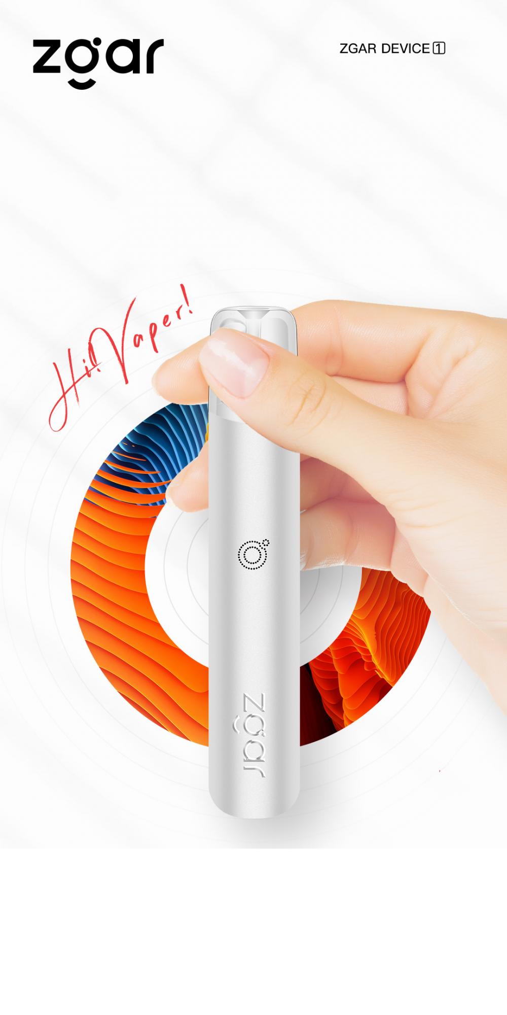

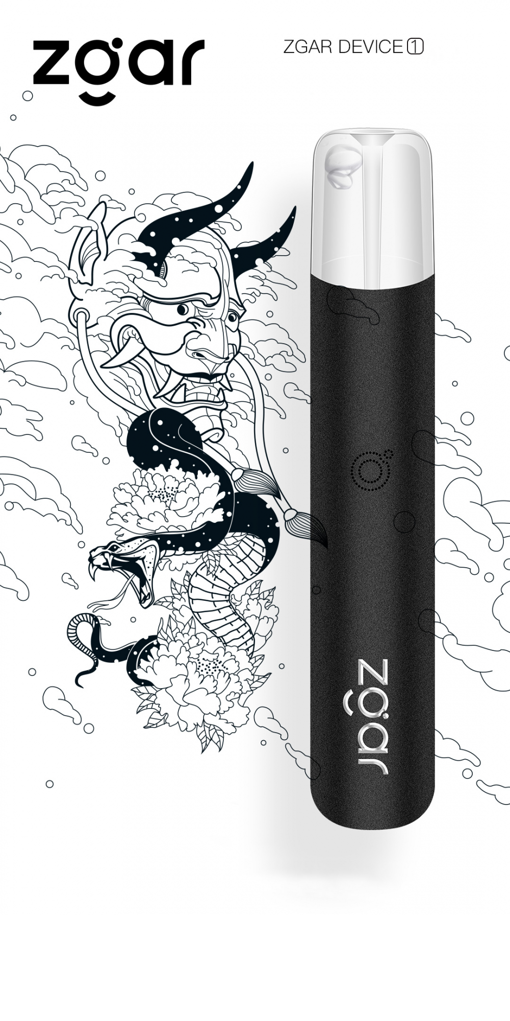
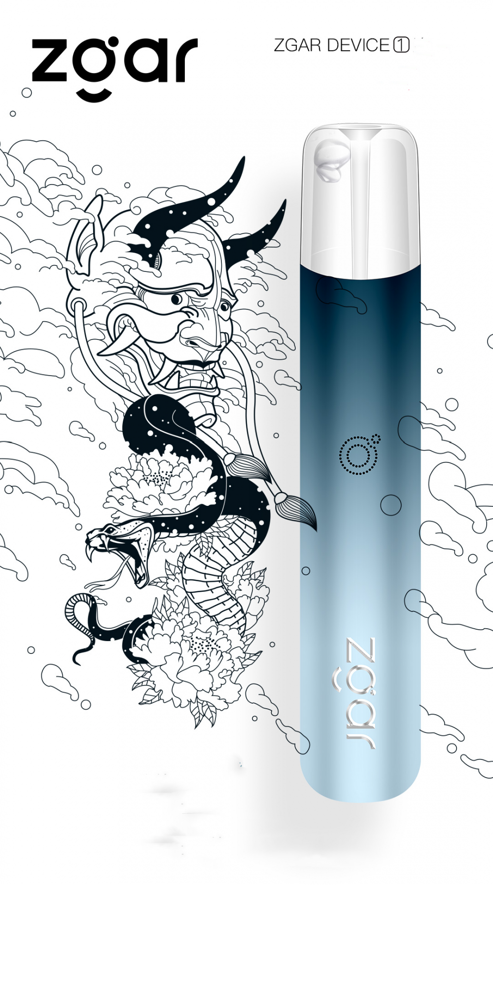
ZGAR Classic 1.0 Disposable Pod Vape,ZGAR Classic 1.0 Disposable Vape Pen,ZGAR Classic 1.0,ZGAR Classic 1.0 Electronic Cigarette,ZGAR Classic 1.0 OEM vape pen,ZGAR Classic 1.0 OEM electronic cigarette.
ZGAR INTERNATIONAL(HK)CO., LIMITED , https://www.szdisposable-vape.com