1. The technical basis of rendering path
Before introducing various lighting rendering methods, you must first introduce the modern graphics rendering pipeline. This is the technical basis for several of the Rendering Paths mentioned below.
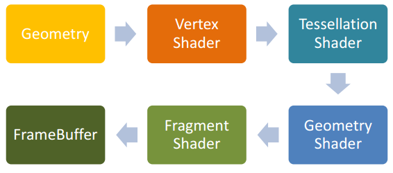
The current mainstream game and graphics rendering engines, including the underlying APIs (such as DirectX and OpenGL), are beginning to support modern graphics rendering pipelines. The modern rendering pipeline is also called the Programmable Pipeline. To put it simply, the part that writes the previous fixed pipeline (such as the processing of the vertices, the processing of the pixel color, etc.) can be customized on the GPU. The advantage of programming is that the user can freely play more space. The disadvantage is that the user must implement many functions.
The following is a brief introduction to the flow of the programmable pipeline. An example of drawing a triangle with OpenGL. First the user specifies three vertices to pass to the Vertex Shader. The user can then choose whether to make a Tessellation Shader (which may be used for tessellation) and a Geometry Shader (which can add or delete geometry information on the GPU). The rasterization is performed immediately, and the rasterized result is passed to the Fragment Shader for pixel level processing. Finally, the processed pixels are passed to the FrameBuffer and displayed on the screen.
2. Several commonly used Rendering Paths
Rendering Path actually refers to the way in which the lighting in the scene is rendered. Since the light source in the scene may be many, even a dynamic light source. So how to achieve the best results in terms of speed and effect is really difficult. With the development of today's graphics cards, people have derived so many Rendering Paths to handle all kinds of lighting.
2.1 Forward Rendering

Forward Rendering is a rendering method that all major engines contain. To use Forward Rendering, you typically perform a lighting calculation for each vertex or pixel in the Vertex Shader or Fragment Shader stage, and calculate each source to produce the final result. Below is the core pseudo code for Forward Rendering.

For example, in the Unity3D 4.x engine, for the circle in the figure below (representing a Geometry), Forward Rendering processing is performed.
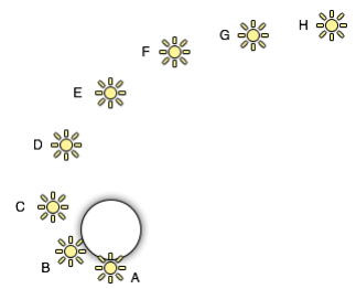
Will get the following processing results
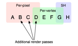
That is, for the four light sources of ABCD we process the illumination for each pixel in the Fragment Shader, for the DEFG source we process the illumination for each vertex in the Vertex Shader, and for the GH source we use the spherical harmonic (SH) function. Process it.
Forward Rendering Advantages and Disadvantages
Obviously, for Forward Rendering, the number of light sources has a great influence on the computational complexity, so it is more suitable for outdoor scenes with less light source (generally only sunlight).
But for multiple light sources, our use of Forward Rendering is extremely inefficient. Because if you calculate lighting in the vertex shader, the complexity will be O(num_geometry_vertexes ∗ num_lights), and if you calculate lighting in the fragment shader, the complexity is O(num_geometry_fragments ∗ num_lights) . The number and complexity of visible light sources increase linearly.
In this regard, we need to make the necessary optimizations. such as
1, more lighting treatment in the vertex shader, because there is a geometry with 10,000 vertices, then for n sources, at least 10000n times in the vertex shader. For processing in the fragment shader, this consumption is more, because for a normal 1024x768 screen, there are nearly 8 million pixels to process. So if the number of vertices is less than the number of pixels, try to illuminate in the vertex shader.
2. If you want to process the light in the fragment shader, we don't have to calculate each light source to process all the pixels once. Because each light source has its own area of ​​action. For example, the active area of ​​the point source is a sphere, and the active area of ​​the parallel light is the entire space. Pixels that are not in this illumination area are not processed. But in doing so, the burden on the CPU side will increase.
3. For a certain geometry, the degree to which the light source acts is different, so some light sources with a particularly small degree of effect may not be considered. A typical example is that only four of the most important light sources are considered in Unity.
2.2 Deferred Rendering
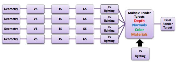
Deferred Rendering, as its name suggests, delays the processing of light processing for a while. The specific method is to place the light after the 3D object has been generated to generate a 2D image. That is to say, the lighting treatment of the object space is put into the image space for processing. To do this, you need an important auxiliary tool - G-Buffer. G-Buffer is mainly used to store the Position, Normal, Diffuse Color and other Material parameters for each pixel. Based on this information, we can perform illumination processing on each pixel in the image space [3]. Below is the core pseudo code for Deferred Rendering.

Here is a simple example.
First we use a texture map that stores various information. For example, the following Depth Buffer is mainly used to determine the distance of the pixel from the viewpoint.
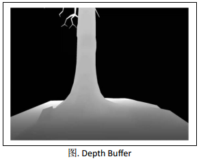
The reflection effect is calculated from the density/intensity scale map of the reflected light.

The figure below shows the normal data, which is critical. The most important set of data for lighting calculations.
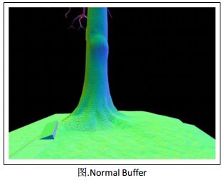
The figure below uses the Diffuse Color Buffer.
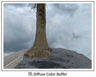
This is the end result of using Deferred Rendering.
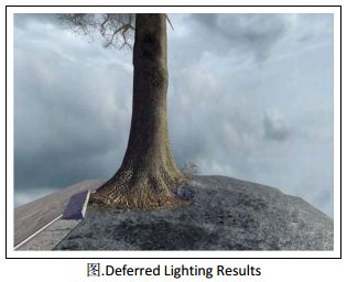
The biggest advantage of Deferred Rendering is that the number of light sources and the number of objects in the scene are completely separated at the complexity level. That is to say, whether the scene is a triangle or a million triangles, the final complexity does not change greatly with the number of light sources. From the pseudo code above, you can see that the complexity of deferred rendering is O(screen_resolution + num_lights).
But the limitations of Deferred Rendering are also obvious. For example, I store the following data in G-Buffer.

In this case, for a normal 1024x768 screen resolution. A total of 1024x768x128bit=20MB is used, which may not be a problem for the current graphics card memory. But the memory used by G-Buffer is still a lot. On the one hand, for low-end graphics cards, such large graphics memory is really resource-intensive. On the other hand, if you want to render a cooler effect, the size of the G-Buffer used will increase, and the magnitude of the increase is also considerable. Incidentally, accessing the bandwidth consumed by G-Buffer is also a flaw that cannot be ignored.
Optimization of Deferred Rendering is also a challenging issue. Here's a quick look at several ways to reduce the bandwidth of Deferred Rendering access. The simplest and easiest to think of is to minimize the access to the G-Buffer data structure, which is derived from the light pre-pass method. Another way is to group multiple lights together and then work together. This method spawns Tile-based deferred Rendering.
2.2.1 Light Pre-Pass
Light Pre-Pass was first mentioned by Wolfgang Engel in his blog [2].
The specific approach is:
(1) Store the Z value and the Normal value only in the G-Buffer. Compared to Deferred Render, Diffuse Color, Specular Color and the material index value of the corresponding position are missing.
(2) In the FS stage, use the above G-Buffer to calculate the necessary light properties, such as Normal*LightDir, LightColor, Specular and other light properties. These calculated lights are alpha-blend and stored in LightBuffer (the buffer used to store light properties).
(3) Finally, the result is sent to the forward rendering rendering method to calculate the final lighting effect.
Compared to the traditional Deferred Render, Light Pre-Pass can be used to render different shades for each different geometry, so the material properties of each object will change more. Here we can see that for the traditional Deferred Render, its second step (see pseudo code) is to traverse each light source, which increases the flexibility of the light source settings, and the third step of Light Pre-Pass is actually forward. Rendering, so you can set the material for each mesh, the two are complementary, there are advantages and disadvantages. Another advantage of Light Pre-Pass is that it is beneficial to use MSAA. Although not 100% use MSAA (unless DX10/11 features are used), it is easy to find edges and sample because of the Z and Normal values.
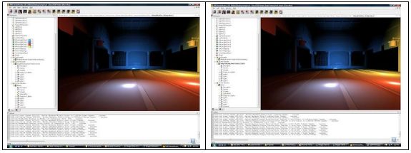
The two images below are drawn using the traditional Deferred Render on the left and are drawn using Light Pre-Pass. These two figures should not be too different in effect.
2.2.2 Tile-Based Deferred Rendering
The main idea of ​​TBDR is to divide the screen into small tiles. Then, based on these Depth, the bounding box of each tile is obtained. The bounding box and light of each tile are intersected, which gives a sequence of lights that have an effect on the tile. Finally, the lighting effect of the tile is calculated according to the obtained sequence.
In contrast to Deferred Render, the light volume of the active area is determined for each light source, and then the pixel of its action is determined, that is, each light source is required to be taken once. With TBDR, just traverse each pixel, let its tile and the light intersect, calculate the light on it, and use G-Buffer for Shading. On the one hand, this reduces the number of light sources to be considered, and on the other hand reduces the bandwidth of access compared to traditional Deferred Rendering.
2.3 Forward+
Forward+ == Forward + Light Culling [6]. Forward+ is very similar to Tiled-based Deferred Rendering. The specific method is to first z-prepass the input scene, that is, to close the write color, and only write the z value to the z-buffer. Note that this step is required for Forward+, and other rendering methods are optional. The next steps are very similar to TBDR, which divides the tiles and calculates the bounding box. Only TBDR does this in G-Buffer, and Forward+ is based on Z-Buffer. The last step actually uses the forward mode, which calculates the lighting effect for each pixel based on the light sequence of its tile in the FS stage. The TBDR uses a deferred rendering based on G-Buffer.
In fact, forward+ runs faster than deferred. We can see that because Forward+ only needs to write the depth buffer, Deferred Render is written to the normal buffer in addition to the depth buffer. In the Light Culling step, Forward+ only needs to calculate which light has an effect on the tile. Deferred Render also handles lighting in this section. In this part, Forward+ is done in the Shading stage. So the Shading stage Forward+ takes more time. But for current hardware, Shading doesn't take much time.
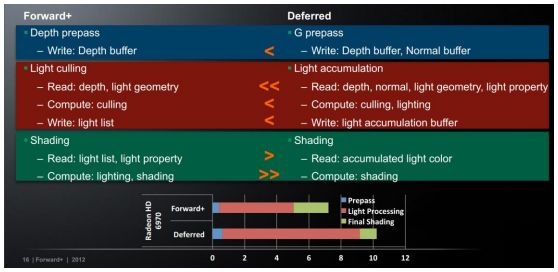
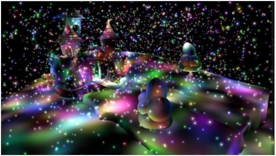
There are many advantages of Forward+. In fact, most of them are the advantages of traditional Forward Rendering itself, so Forward+ is more like a Rendering Path that combines the advantages of various Rendering Paths.
3. Summary
First we list the Rendering Equation and then compare Forward Rendering, Deferred Rendering and Forward+ Rendering.
3.1 Rendering Equation
There is an incident light at the point x, the light intensity is Le, and the incident angle is wi. The angle of incidence is calculated according to the functions f and Le). Note that n here is a total of n light sources in the scene.

3.2 Forward Renderng
Since Forward itself does not support multiple light sources, the processing of each point x is no longer considered for all n light sources, only a small number or selected m light sources are considered. It can be seen that such lighting effects are not perfect. In addition, the V' (wo) of each ray is not calculated.

3.3 Deferred Rendering
Since Deferred Rendering uses light culling, you don't have to traverse all the lights in the scene, just traverse the n light sources after light culling. And Deferred Rendering separates the parts of the calculated BxDF separately.

3.4 Forward+ Rendering
It can be seen that the biggest difference between Forward+ and Forward is that the selection of the light source has been improved.

Film Covered Flat Aluminium Wire
| About Film Covered Flat Aluminium Wire |
Fiber glass film covered enameled aluminum flat wire
The product is the premium copper or aluminum to be enameled, then to be wrapped with polyester film or polyimide film so as to enhance the breakdown voltage of enameled wire. It has the advantages of thin insulation thickness, high voltage resistance. The product is the ideal material for electrical instruments of small size, large power, high reliability.
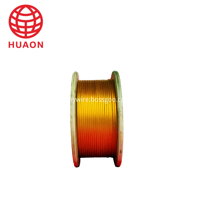
Copper or Aluminum rectangular Wire
Narrow side size a : 1.00 mm-5.60 mm
Broad side size b : 2.00 mm-16.00 mm
Film Covered Copper Wire,Film Covered Flat Aluminium Wire,Covered Flat Magnet Wire,Fiberglass Covered Wire
HENAN HUAYANG ELECTRICAL TECHNOLOGY GROUP CO.,LTD , https://www.huaonwire.com