This system uses 430 microcontroller, FPGA. The electromagnetic waves of different frequencies are received through the antenna, and the generation of the local oscillator frequency is controlled by the single-chip microcomputer, so that the stations of different frequencies are selected, the signals obtained by the mixing are demodulated by the FPGA, and finally the sound is emitted by the speaker through the power amplifier. The system pays attention to the details of low-power processing and high cost performance in the design.
The main features of this design:1. MB1504 control generates local oscillator, which is efficient, stable and simple.
2. The FPGA has good stability and fast processing speed.
3. Digital radios receive more accurate data and receive more accurate radio stations.
1. Program design and argumentation1.1 main control system selection
Solution 1: Adopt high-performance embedded systems, such as ARM. If this scheme is adopted, the data processing and control functions can be well solved, but the ARM is expensive and has little contact in the undergraduate stage, and the difficulty in completing in a short time is relatively large.
Option 2: Use a general-purpose single-chip microcomputer, such as 51 single-chip microcomputer. However, the internal resources of the 51 MCU are not enough, and many functions cannot be realized.
Solution 3: It is implemented by 430 high-performance single-chip microcomputer to process and control the local oscillator frequency.
Considering the practicability and cost performance of the solution, we use M430F1611 single-chip microcomputer, which can realize high-speed operation, large storage space, low price and high cost performance.
1.2 local oscillator selection
Solution 1: Select discrete components to match, but this method is too difficult, and the error interference is very large.
Option 2: Full selection of dedicated chips with microcontroller control. This method is simple but expensive.
Option 3: A vco circuit using a combination of a digital phase-locked loop chip and discrete components.
Taking into account factors such as price, operating frequency and sensitivity. This system uses MB1504 phase-locked loop chip and discrete components to take the VCO.
1.3 frequency conversion selection
Option 1: Use one frequency conversion. This method is simple and easy to implement, but has higher requirements for the backend AD.
Option 2: Multiple conversions are used. The overall design is more complicated, the errors will be large, and the implementation is difficult.
Consider the radio's high data requirements and overall performance. This system uses one frequency conversion, and the chip uses NE602.
1.4 data processing module selection
Solution 1: Using a dedicated demodulation chip, this method is simple, but the expansion and development are very poor.
Solution 2: Demodulation with FPGA chip, this scheme is clear and simple in structure, good in stability, but expensive.
The system uses FPGA chip as demodulation to ensure the development and accuracy of the system.
1.5 audio processing
Solution 1: Using a triode for amplification, the effect is not good and complicated.
Option 2: Use a dedicated power amplifier chip.
Considering this, the system uses the power amplifier chip LM386.
summary:
After several careful arguments and comparisons, we decided that the main modules of this system are as follows:
Audio processing solution: LM386.
Main controller: MSP430 microcontroller.
Local oscillator circuit scheme: VCO of MB1504+ discrete components.
Frequency conversion module: NE602.
Data Processing Module: FPGA Minimum System Board.
2. Circuit design2.1 system composition principle
The system consists of local oscillator module, frequency conversion module, main control single chip microcomputer, FPGA demodulation module, audio module, AD module, DA module and so on.
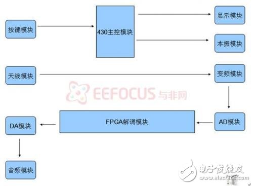
Figure 2.1 System composition schematic
2.2 local oscillator circuit
The MB1504 phase-locked loop and the voltage-controlled oscillator are controlled by a single-chip microcomputer to generate the required frequency.
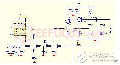
Figure 2.2 Schematic diagram of the local oscillator circuit
2.3 frequency conversion module
The frequency generated by the local oscillator and the frequency received by the antenna are mixed and amplified by the NE602.
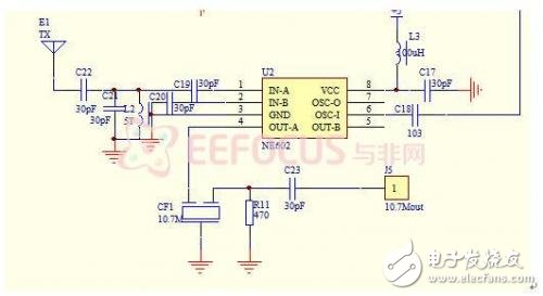
Figure 2.3 Schematic diagram of the inverter module
2.4AD, DA module
The analog signal after the frequency conversion is demodulated by the AD into the FPGA, and then demodulated and then converted into an analog signal by the DA.
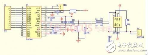
Figure 2.4.1 DA module
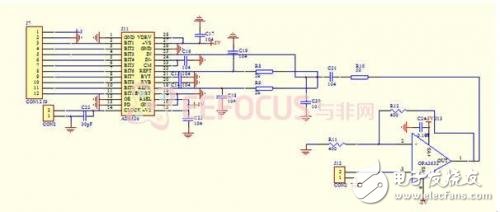
Figure 2.4.2 AD module
2.5 sound module
The analog signal is amplified by the power amplifier and sent to the horn to be restored to a sound signal.
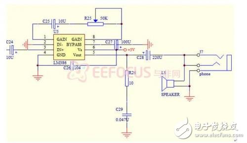
Figure 2.5 power amplifier circuit
3. software design3.1FPGA demodulation
 ,
,  For quadrature signals, cM Signal is the digital cM IF data sampled by the ADC. After two orthogonal multiplications, CIC is extracted. The cIo low-pass filter is used to filter the sum frequency components generated by orthogonal multiplication, including speech. The zero IF signal component in the message is preserved. The orthogonal zero-IF components are then cross-multiplied by the derivative, and the difference is the useful speech information.
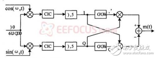
Figure 3.1 FPGA IF Demodulation
3.2 single chip control
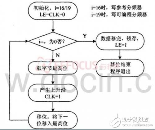
Figure 3.2 MCU send flow chart
4. System test1. Overall testing.
The test function receives 7 stations and basically implements the required functions.
2. Error analysis
Some stations can't accept it, or the sound is unclear. There are two reasons for analysis:
1) AD has an impact on information integrity due to undersampling.
2) The interference signal carried by the antenna receiving signal is not completely filtered out and causes interference.
5. Design summary
This work FPGA and 430 are the core components. By controlling the local oscillator frequency, different radio signals are selected, and the 10.7M frequency signal is generated by mixing, and then demodulated by FPGA, and the amplifier is amplified and restored into sound. In the design, we try to use low-power devices, strive to economical and streamlined hardware circuits, and give full play to the flexible and convenient software control to meet the design requirements.
Android is an open source mobile operating system based on Linux platform released by Google at the end of 2007, and then improved for use in netbooks and MIDs. The platform consists of operating system, user interface and application software, and is claimed to be the first truly open and complete mobile software for mobile terminals.
To put it simply, the Android system is actually a very open system. It can not only realize the functions of the most commonly used notebook computers, but also realize various directional operations like mobile phones. Moreover, it is specially designed for mobile phones. The operating system developed for equipment has advantages in system resource consumption and human-computer interaction design. It is an operating system that combines traditional and advanced advantages.
New Android Tablet,Android Tablet,New Android Tablet
Jingjiang Gisen Technology Co.,Ltd , https://www.gisentech.com